Solar Cells, Solar Strings and Solar Modules

A technology of solar cells and solar cells, which is applied to electrical components, circuits, photovoltaic power generation, etc., can solve the problems of high manufacturing costs and complicated processes, and achieve the effects of reducing processing steps, small node volume, and maintaining photoelectric conversion efficiency

Active Publication Date: 2017-05-24
LDK SOLAR XINYU HI TECH XINYU CO LTD
View PDF4 Cites 1 Cited by
  • Summary
  • Abstract
  • Description
  • Claims
  • Application Information

AI Technical Summary

Problems solved by technology

[0004] However, this solar cell also has the following disadvantages: because there are many fine grid lines 94 on the front of the cell, it is necessary to process a lot of conductive holes 98 on the cell to connect to the negative electrode 96 on the back of the cell, resulting in complicated procedures and high manufacturing costs.

Method used


Image

  • Solar Cells, Solar Strings and Solar Modules
  • Solar Cells, Solar Strings and Solar Modules
  • Solar Cells, Solar Strings and Solar Modules

Examples


Embodiment 1

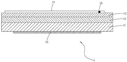
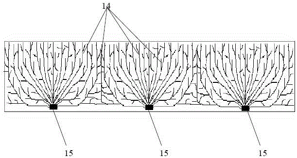
[0034] Such as figure 2 with image 3 As shown, the solar battery sheet 1 provided by Embodiment 1 of the present invention has a length of 3-40 cm, a width of 1-15 cm, and a thickness of 0.08-2 mm. The solar battery sheet 1 includes silicon wafers 11, The diffusion layer 12 and the anti-reflection film 13, the upper surface of the anti-reflection film 13 is provided with several thin grid lines 14 for conducting current, the several thin grid lines 14 are intersected and converged with at least one node 15, the silicon wafer 11 At least one back electric field 16 is provided on the surface, wherein the thin grid line 14 and the node 15 are the negative pole of the solar battery 1 , and the back electric field 16 is the positive pole of the solar battery 1 .

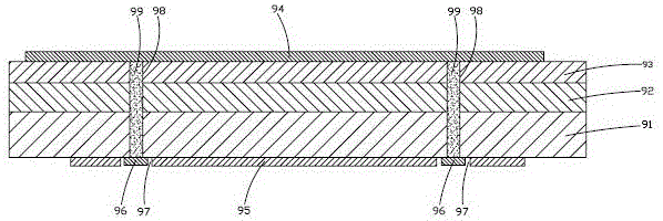
[0035] Such as Figure 4 As shown, the connection mode between the two solar cells 1 provided in the first embodiment is: the node 15 on the front of one solar cell 1 is connected to the back of the back of another ad...

Embodiment 2

[0047] Such as Figure 5 with Image 6 As shown, a solar cell 2 provided by Embodiment 2 of the present invention has a length of 3-40 cm, a width of 1-15 cm, and a thickness of 0.08-2 mm. The solar cell 2 includes silicon wafers 21, The diffusion layer 22 and the anti-reflection film 23, the upper surface of the anti-reflection film 23 is provided with several thin grid lines 24 for conducting current, and the several thin grid lines 24 are intersected and converged with at least one node 25. The surface is provided with at least one back electrode 26 and a back electric field 27, wherein the fine grid line 24 and the node 25 are the negative pole of the solar cell 2, and the back electrode 26 and the back electric field 27 are the positive pole of the solar cell 2.

[0048] Such as Figure 7 As shown, the connection mode between the two solar cells 2 provided in the second embodiment is: the node 25 on the front side of one solar cell 2 is connected to the back side of the...

Embodiment 3

[0060] Such as Figure 8 with Figure 9 As shown, a solar cell 3 provided by Embodiment 3 of the present invention has a length of 3-40 cm, a width of 1-15 cm, and a thickness of 0.08-2 mm. The solar cell 3 includes silicon wafers 31, Diffusion layer 32 and anti-reflection film 33, the upper surface of anti-reflection film 33 is provided with several thin grid lines 34 for conducting current, the first half of several thin grid lines 34 are arranged parallel to each other, and the second half converges into at least one junction At point 35 , at least one back electric field 36 is provided on the lower surface of the silicon wafer 31 . Wherein, the thin grid line 34 and the node 35 are the negative pole of the solar cell 3 , and the back electric field 36 is the positive pole of the solar cell 3 .

[0061] Such as Figure 10 As shown, the connection mode between the two solar cells 3 provided in the third embodiment is: the node 35 on the front side of one solar cell 3 is c...


PUM


Abstract

The invention relates to a solar cell slice. Current generated by the solar cell slice is converged to a node by fine grid lines and then is conveyed by the node onto a back electrode or a back electric field on the back surface of another adjacent cell slice through a convergence belt. The invention has the beneficial effects that a conductive hole is prevented from being arranged on the cell; expensive conductive paste is not required to be filled; no complicated electrode connection is required on the back surface of the cell slice; and while the manufacturing cost is reduced, the photoelectric conversion efficiency equivalent to that of a highly-efficient solar cell is kept. All the fine grid lines are arranged crosswise and are converged into at least one node; and the current generated by the cell slice can be conveyed from the fine grid line with the shortest length to the node, so that the resistance is minimum when the current is conveyed on the fine grid line, thereby reducing the electric energy loss and improving the electric energy utilization rate of the cell slice. The node of the solar cell slice has small volume, so that the light shielding area on the front surface of the cell slice is reduced, and the effective illumination surface on the front surface of the cell slice is increased, thereby improving the power generating capacity of the cell slice within the unit area. The invention also provides a cell string and a cell module using the solar cell slice.

Description

technical field [0001] The invention belongs to the field of photovoltaic or semiconductor, and in particular relates to a solar battery sheet, a solar battery string and a solar battery module using the solar battery sheet. Background technique [0002] Such as figure 1 As shown, the existing solar cells include a silicon wafer 91, a diffusion layer 92, and an anti-reflection film 93 stacked in sequence. Several thin grid lines 94 for conducting current are arranged on the upper surface of the anti-reflection film 93. The grid lines 94 are arranged parallel to each other, and at least one positive electrode 95 and at least one negative electrode 96 are provided on the lower surface of the silicon chip 91, and the positive electrode 95 and the negative electrode 96 are separated by an insulating groove 97. The anti-reflection film 93 is provided with at least one through conductive hole 98 , and the conductive hole 98 is filled with a conductive paste 99 , and each fine gri...

Claims


Application Information

Patent Timeline
Patent Type & Authority Patents(China)
IPC IPC(8): H01L31/0224H01L31/048H01L31/042
CPCY02E10/50
Inventor 中野研吾孙李媛
Owner LDK SOLAR XINYU HI TECH XINYU CO LTD
Why Eureka
Try Eureka