Solar cell, solar cell string and solar cell module

A technology of solar cells and solar cells, applied in electrical components, circuits, photovoltaic power generation, etc., can solve the problems of loss and high packaging loss of shingled components, and achieve the effects of optimizing design, increasing power generation, and reducing spacing

Inactive Publication Date: 2020-03-27
YINGLI ENERGY CHINA
View PDF4 Cites 0 Cited by
  • Summary
  • Abstract
  • Description
  • Claims
  • Application Information

AI Technical Summary

Problems solved by technology

[0004] At present, the technology of connecting single cells into battery strings is the lamination technology. The lamination components use the scribing technology to cut the redesigned cells into small pieces with reasonable graphics. Generally, the small pieces are 1 / 5 dicing or 1 / 2 6 Scribing, and then superimposing and arranging each small piece, using conductive glue to weld the pieces to form a string, and then laminating them into components after series-parallel typesetting; the technical shortcomings of the shingling technology are as follows: (1) Lamination In the process of module design, although the same module area can be increased by about 10% of the cells, but because there is an overlap width of 1mm to 1.5mm between the sheets, the overlap width is equivalent to the loss of 2 to 3 small cells, so the shingled module (2) In order to reduce debris in the process, the shingling technology uses conductive adhesive, the conductivity of the conductive adhesive is two to three orders of magnitude lower than that of ordinary pure metal conductor materials, so the fill factor of the shingling module is higher. lower than conventional components

Method used


Image

  • Solar cell, solar cell string and solar cell module
  • Solar cell, solar cell string and solar cell module
  • Solar cell, solar cell string and solar cell module

Examples


Embodiment Construction

[0030] In order to make the technical problems, technical solutions and beneficial effects to be solved by the present invention clearer, the present invention will be further described in detail below in conjunction with the accompanying drawings and embodiments. It should be understood that the specific embodiments described here are only used to explain the present invention, not to limit the present invention.

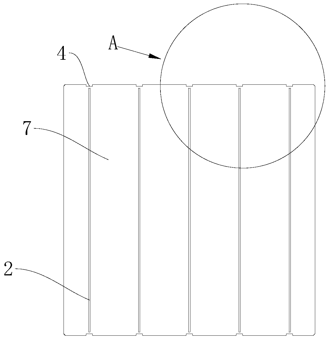
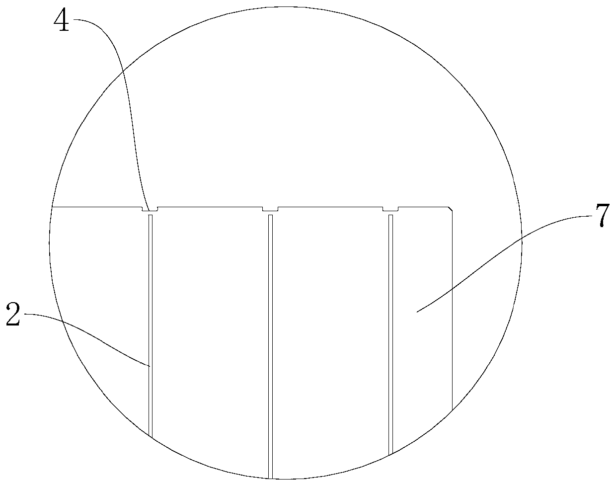
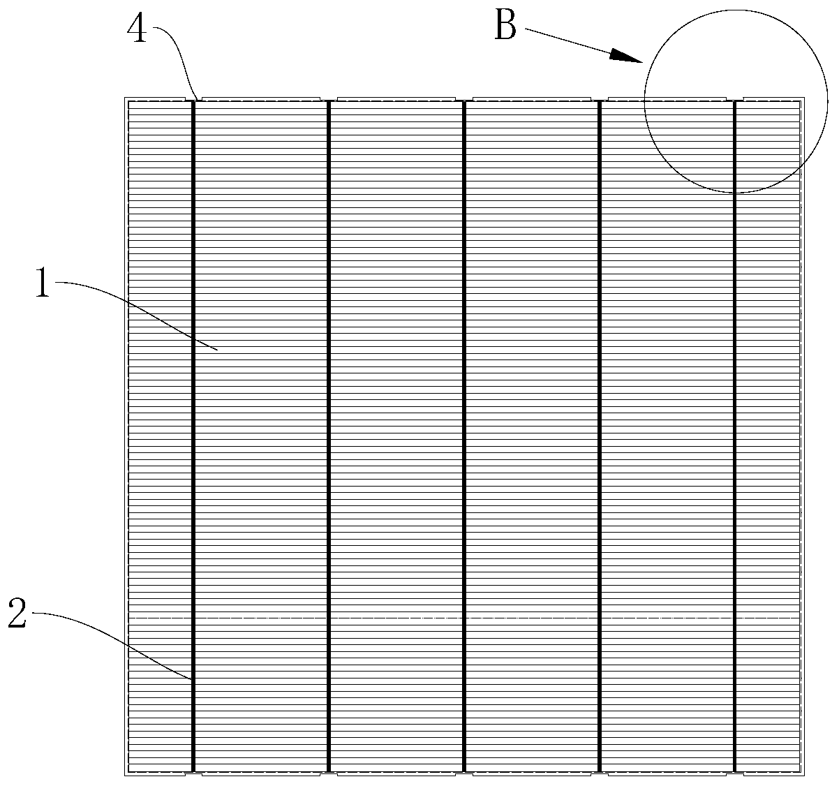
[0031] Please also refer to Figure 1 to Figure 4 , a solar battery sheet provided by the present invention will now be described. Said solar battery sheet comprises a silicon chip 1, a suede surface, a doped layer and an anti-reflection film layer formed sequentially on the front side of the silicon chip 1, and the front side of the silicon chip 1 is provided with a number of parallel devices for collecting current. The main grid lines 2 and a number of cut-out groups for the passage of the solder ribbon 8, each main grid line 2 corresponds to each cut-hole group...


PUM

PropertyMeasurementUnit
Lengthaaaaaaaaaa
Widthaaaaaaaaaa

Abstract

The invention provides a solar cell, a solar cell string and a solar cell module. The invention belongs to the technical field of photovoltaic modules. The solar cell comprises a silicon wafer, and atextured surface, a doped layer and an antireflection film layer which are sequentially formed on the front surface of the silicon wafer, wherein the front surface of the solar cell is also provided with a plurality of main grid lines which are arranged in parallel and are used for collecting current, and a plurality of cut hole groups which are used for a solder strip to pass through, and the main grid lines are in one-to-one correspondence with the cut hole groups, and each cut hole group comprises two cut holes which are respectively arranged at the edges of two sides of the silicon wafer;and the main grid lines corresponding to the cut hole groups are positioned between the two cut holes in the cut hole groups. According to the solar cell, the cut holes are formed in the edge of the cell, and the center positions of the cut holes correspond to the center line positions of the cell printing main grid lines; and in the series welding process of the cell, the inter-piece welding strips connecting every two adjacent cells penetrate through the cut holes, and the distance between the cells is reduced, and the unit area power generation power of a photovoltaic module is increased.

Description

technical field [0001] The invention belongs to the technical field of photovoltaic modules, and more specifically relates to a solar battery sheet, a battery string and a solar battery module. Background technique [0002] In order to improve the power generation efficiency of a single module and reduce the cost of the system, various module manufacturers in the photovoltaic industry have developed various technologies to increase the power generation per unit area of ​​the module. At present, the conventional interconnection technology is to use tin-coated copper strips to connect single cells into battery strings, and the battery strings are connected in series or in parallel to form components. [0003] When the ribbon is connected to the positive and negative electrodes of the battery, a certain distance needs to be designed for the bending position of the ribbon between two adjacent battery sheets, that is, the sheet spacing, to reduce the influence of the ribbon stres...

Claims


Application Information

Patent Timeline
IPC IPC(8): H01L31/05H01L31/0224
CPCH01L31/022433H01L31/0508Y02E10/50
Inventor 麻超杨燕苑北海郑炯王帆王会晓尚琪陈志军王丹田思王中河
Owner YINGLI ENERGY CHINA
Why Eureka
Try Eureka