Image brightness compensation method for image coding

A technology of image brightness and compensation method, applied in the field of image processing, can solve the problems of slow speed, complex algorithm, low compression efficiency, etc., to achieve the effect of fast running speed, simple algorithm, and improved compression efficiency

Inactive Publication Date: 2010-05-19
HARBIN INST OF TECH
View PDF0 Cites 16 Cited by
  • Summary
  • Abstract
  • Description
  • Claims
  • Application Information

AI Technical Summary

Problems solved by technology

[0007] The purpose of the present invention is to provide an image brightness compensation method for image coding in order to solve the problems that t

Method used


Image

  • Image brightness compensation method for image coding
  • Image brightness compensation method for image coding
  • Image brightness compensation method for image coding

Examples


specific Embodiment approach 1

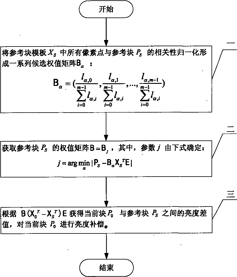
[0020] Specific implementation mode one: the following combination Figure 1 to Figure 5 Describe this implementation mode, this implementation mode comprises the following steps:

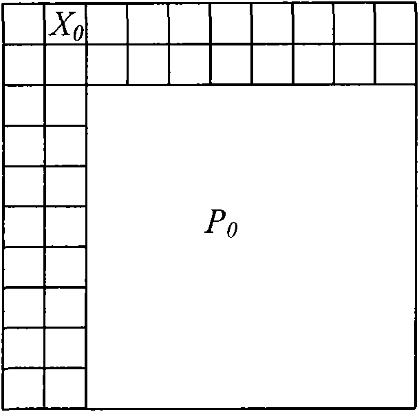
[0021] Define a certain macroblock of the current frame image as the current block P 0 , in the current frame with the current block P 0 The adjacent L-shaped neighborhood is the current block template X 0 , the current block template brightness value matrix is ​​X 0 , the current block template brightness value matrix is ​​X 0 The transpose matrix of X is 0 T ,

[0022] Define the previous frame image and the current block P 0 The macroblock at the same position is the reference block P S , in the previous frame image with the reference block P S The adjacent L-shaped neighborhood is the reference block template X S , the reference block P S The brightness value matrix of P S , the reference block template luminance value matrix is ​​X S , the reference block template luminance value ...

specific Embodiment approach 2

[0051] Embodiment 2: The difference between this embodiment and Embodiment 1 is that the distance between two adjacent discrete points of angle α is 10°-18°, and the other is the same as Embodiment 1.

[0052] Figure 5 The rate-distortion comparison results on the Race1 sequence are given, where the horizontal axis represents the average number of bits per frame, and the vertical axis represents the average peak signal-to-noise ratio (PSNR) per frame. MVC is the result without brightness compensation, and MVC+ICT (Illumination Compensation Template) is the result of template-based brightness compensation. It can be seen from the figure that the present invention has an obvious effect on improving the compression efficiency of multi-viewpoint video coding.

specific Embodiment approach 3

[0053] Embodiment 3: The difference between this embodiment and Embodiment 1 is that the distance between two adjacent discrete points of angle α is 15°, and the others are the same as Embodiment 1.

[0054] This embodiment gives a specific example, the distance between two adjacent discrete points of angle α is 15°, and the values ​​of angle α are 0, 15, 30, 45, 60, 75, 90, 105, 120 , 135, 150, 165, according to these discrete values, 12 candidate weight matrices B are obtained α value for use.


PUM


Abstract

The invention discloses an image brightness compensation method for image coding, belongs to the field of image processing, and solves the problems of complexity, low speed and low compression efficiency of the conventional algorithm for performing brightness compensation for multi-viewpoint video coded images. The image brightness compensation method comprises the following steps: determining brightness difference between a current block P0 and a reference block PS by comparing the brightness difference between a current block template X0 and a reference block template XS, thereby realizing the brightness compensation for the current block; and utilizing a series of solved candidate weight matrixes B alpha, solving the optimal Bj and assigning the optimal Bj to weight matrixes B of the reference block PS, thereby solving the brightness difference between the current block template X0 and the reference block template XS according to B(X0T-XST), which serves as the brightness difference between the current block P0 and the reference block PS for brightness compensation.

Description

technical field [0001] The invention relates to an image brightness compensation method for image coding, which belongs to the field of image processing. Background technique [0002] Due to the advancement of video acquisition technology and video display technology, 3D video is gradually accepted by consumers due to its unique advantages. Through 3D video technology, people can interactively select the viewpoint, so that they can observe the scene of the real world from the angle that people like. Usually, 3D video is represented by multiple viewpoints, and each viewpoint is a traditional 2D video sequence obtained by a camera. Multi-view video coding (MVC) is a key technology in the 3D video transmission system using multi-view representation, which can effectively reduce the transmission bandwidth and the computational complexity of the decoding end. [0003] In a multi-viewpoint video coding system, due to the influence of camera parameters and the change of camera po...

Claims


Application Information

Patent Timeline
IPC IPC(8): H04N7/26H04N7/32H04N19/186H04N19/597
Inventor 赵德斌李晓明刘绍辉姜峰
Owner HARBIN INST OF TECH
Why Eureka
Try Eureka