Thin-film ultrasonic transducer and preparation method thereof

A thin-film ultrasonic and transducer technology, applied in the direction of the fluid using vibration, can solve the problem of low sensitivity, and achieve the effect of increasing the received signal

Inactive Publication Date: 2010-05-26
INST OF ACOUSTICS CHINESE ACAD OF SCI
View PDF1 Cites 57 Cited by
  • Summary
  • Abstract
  • Description
  • Claims
  • Application Information

AI Technical Summary

Problems solved by technology

[0007] The purpose of the present invention is to provide a thin-film ultrasonic transducer and its preparation method in or...

Method used


Image

  • Thin-film ultrasonic transducer and preparation method thereof
  • Thin-film ultrasonic transducer and preparation method thereof
  • Thin-film ultrasonic transducer and preparation method thereof

Examples


Embodiment 1

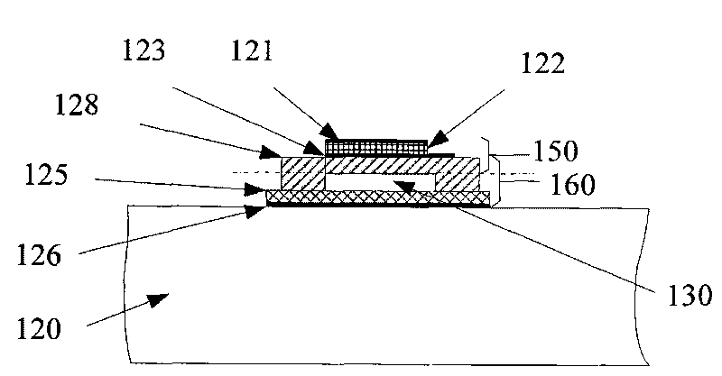
[0062] image 3 It is a structural schematic diagram of an embodiment of the thin-film piezoelectric ultrasonic transducer of the present invention. Its structure of thin-film acoustic transducer provided by the invention is as follows: image 3 As shown: it includes a flat part 150 containing a piezoelectric layer, a peripheral closed cavity 130 below the flat part 150 , and a capacitive second electrode 126 prepared with an insulating layer 125 on top. The flat part 150 containing the piezoelectric layer is a bendable piezoelectric vibrating membrane, including a support layer 128, a piezoelectric first electrode 123 located on the support layer 128, a piezoelectric first electrode 123 located on the piezoelectric first electrode 123 Layer 122 and the piezoelectric second electrode 121 positioned on the piezoelectric layer 122 constitute a piezoelectric acoustic transducer unit 150, so the function of a traditional piezoelectric thin film ultrasonic transducer can be realiz...

Embodiment 2

[0076] Figure 8 It is a structural schematic diagram of an embodiment of the thin-film piezoelectric ultrasonic transducer of the present invention. Its structure of thin-film acoustic transducer provided by the invention is as follows: Figure 8 As shown: it includes a flat part 250 containing a piezoelectric layer, a peripheral closed cavity 230 below the flat part 250, and a capacitive second electrode 226 prepared with an insulating layer 225 on the top, and the capacitive second electrode 226 is low. resistive silicon substrate. The flat member 250 containing a piezoelectric layer is a bendable piezoelectric vibrating membrane, including a support layer 228 , a piezoelectric first electrode 223 located on the support layer 228 , and a piezoelectric first electrode 223 located on the piezoelectric first electrode 223 . Layer 222 and the piezoelectric second electrode 221 positioned on the piezoelectric layer 222 constitute a piezoelectric acoustic transducer unit 250, s...

Embodiment 3

[0086] Figure 12 It is a structural schematic diagram of an embodiment of the thin-film piezoelectric ultrasonic transducer of the present invention. Its structure of thin-film acoustic transducer provided by the invention is as follows: Figure 12 As shown: it includes a flat part 350 containing a piezoelectric layer, a peripheral closed cavity 330 below the flat part 350, and a capacitive second electrode 300 prepared with an insulating layer 325 on the top, and the capacitive second electrode 300 is low. resistive silicon substrate. The flat member 350 containing a piezoelectric layer is a bendable piezoelectric vibrating membrane, including a support layer 328 , a piezoelectric first electrode 323 located on the support layer 328 , and a piezoelectric first electrode 323 located on the piezoelectric first electrode 323 . Layer 322 and the piezoelectric second electrode 321 positioned on the piezoelectric layer 322 constitute a piezoelectric acoustic transducer unit 350,...


PUM

PropertyMeasurementUnit
Thicknessaaaaaaaaaa
Thicknessaaaaaaaaaa
Thicknessaaaaaaaaaa

Abstract

The invention relates to a thin-film ultrasonic transducer and a preparation method thereof. The thin-film ultrasonic transducer comprises a capacitance transducer unit, wherein the capacitance transducer unit comprises a capacitance second electrode (126), an insulating layer (125), an air micro-gap (130), a supporting component (128) and a piezoelectric first electrode (123) from bottom to top. The thin-film ultrasonic transducer is characterized in that the thin-film ultrasonic transducer also comprises a piezoelectric layer (122) positioned on the piezoelectric first electrode (123) and a piezoelectric second electrode (121) positioned on the piezoelectric layer (122) from bottom to top in turn; the supporting component (128) is a bendable piezoelectric vibrating diaphragm; and an inward-concave position in the lower center of the supporting component and the insulating layer (125) form a closed air micro-gap cavity. The invention also provides three methods for preparing the thin-film ultrasonic transducer, prepares all the components from bottom to top in turn, and particularly provides a plurality of modes for preparing the air micro-gap.

Description

technical field [0001] The invention belongs to the field of ultrasonic transducers, in particular, the invention relates to a thin-film ultrasonic transducer and a preparation method thereof. Background technique [0002] Acoustic transducers and transducer arrays are widely used in many fields of social life and industrial production. Ultrasonic transducers and transducer arrays are the most critical sensing components in medical ultrasonic imaging and industrial ultrasonic testing and monitoring equipment. Examples include ultrasound examinations of the heart, abdominal organs, and fetuses in medicine. Industrial non-destructive testing of steel pipes, welds, etc. Ultrasonic imaging is to transmit ultrasonic signals to the target through the ultrasonic probe, receive the reflected signals at different positions of the target, analyze and process the characteristics of the reflected signals of the target, and obtain ultrasonic imaging information. The image quality of u...

Claims


Application Information

Patent Timeline
IPC IPC(8): B06B1/06
Inventor 郝震宏乔东海
Owner INST OF ACOUSTICS CHINESE ACAD OF SCI
Why Eureka
Try Eureka