Vehicle moving-magnet follow-up steering headlight system

A follow-up steering and magnetic technology, applied in vehicle components, optical signals, signal devices, etc., can solve the problems of complex structure, easy failure, and high manufacturing cost, and achieve reliable safety performance, low cost, and small space. Effect

Inactive Publication Date: 2010-05-26
胡宇峰
View PDF0 Cites 3 Cited by
  • Summary
  • Abstract
  • Description
  • Claims
  • Application Information

AI Technical Summary

Problems solved by technology

When driving at night, when the vehicle is turning, the driver's line of sight can only be within the range of the lights of the car. If there is an obstacle in the blind spot where the light fails to reach when the car is turning, it will not be found in time, which will cause accidents.
Therefore, there is a follow-up steering device in existing automobiles, which is mainly composed of lamps, brackets, controllers, control circuits, steering motors and positioning gears. The most important thing is that when upgrading the existing car lights, the original car lights of the existing cars must be replaced, which will lead to changes or reimbursement of many lamps and lamp molds, making it difficult to promote

Method used


Image

  • Vehicle moving-magnet follow-up steering headlight system
  • Vehicle moving-magnet follow-up steering headlight system
  • Vehicle moving-magnet follow-up steering headlight system

Examples


Embodiment 1

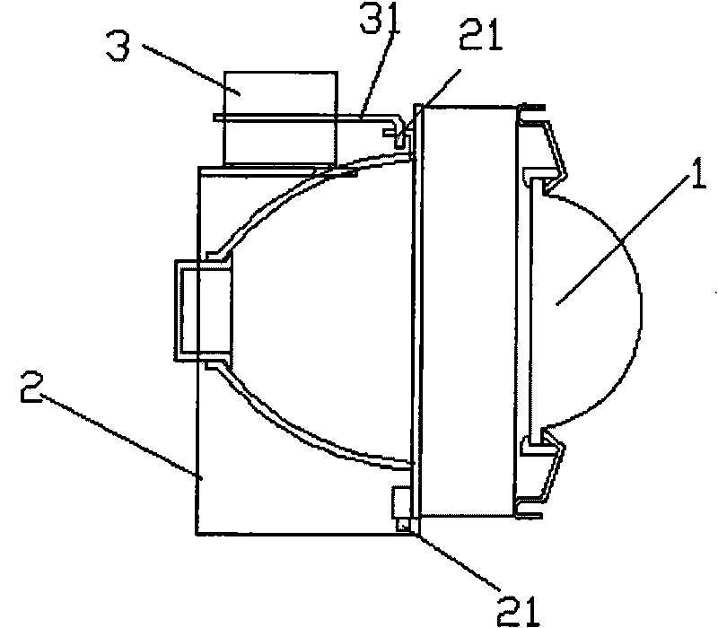
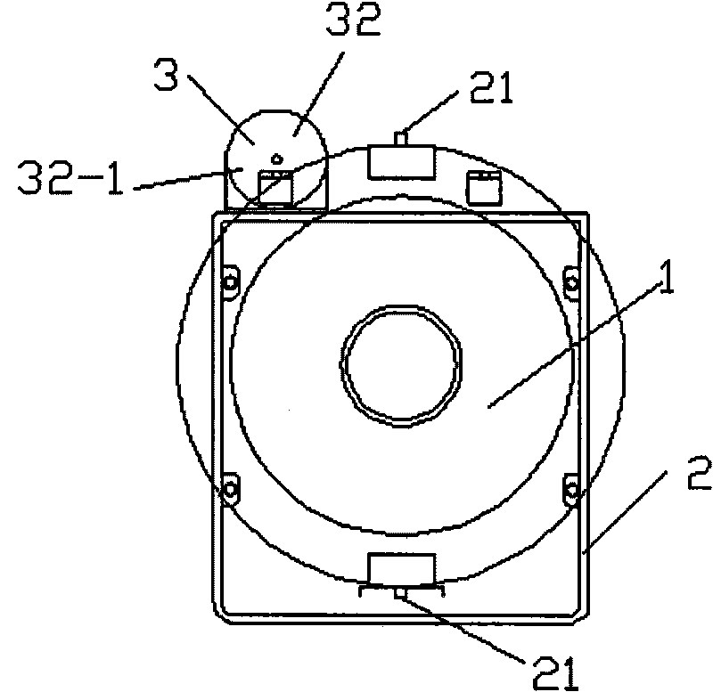
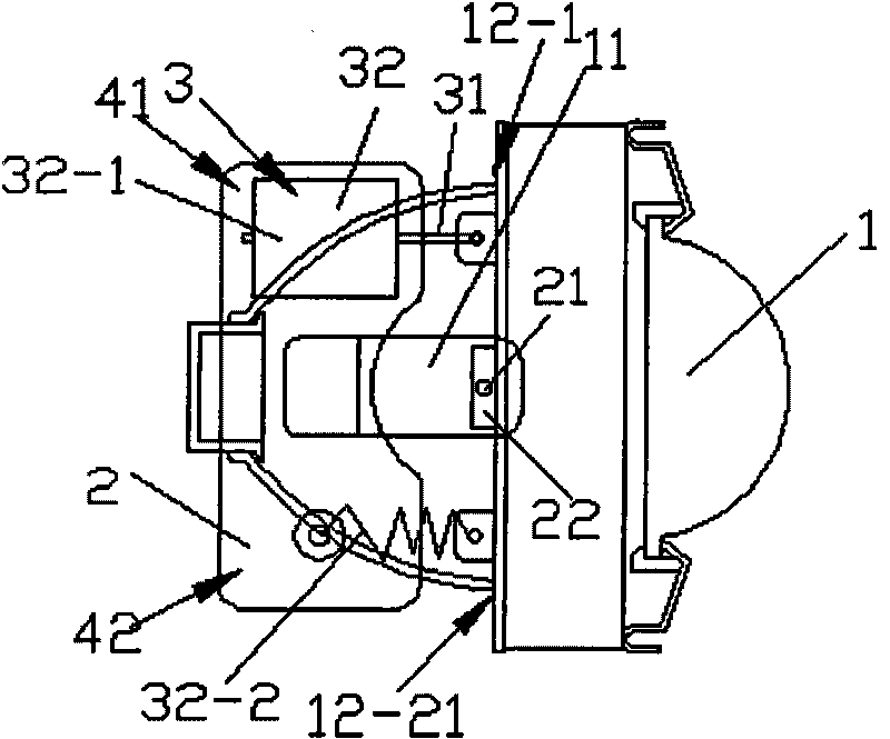
[0021] like Figure 1 to Figure 3 As shown, the vehicle magnetic follow-up steering headlight system of the present invention includes a lamp 1, a bracket 2 and a power mechanism 3, and the bracket 2 is a fixing frame for fixing the lamp 1 and the motor mechanism 3. A connecting plate 11 is arranged on the upper and lower sides of the frame, and a connecting piece 22 is arranged on the upper and lower ends of the lamp 1 respectively. A swingable structure is formed on the bracket 2 . The above-mentioned power mechanism 3 includes a single solenoid valve power mechanism 32 with a pull rod 31 . The power mechanism 3 is fixedly installed on the bracket 2 to form a linkage structure with the lamp 1 . The single solenoid valve power mechanism 32 is made up of a solenoid valve 32-1 and a spring 32-2. The solenoid valve 32-1 is fixed on one side 41 of the bracket 2, and is connected to one side 12-1 of the lamp 1 by a pull rod 31; one end of the spring 32-2 is fixed on the other sid...

Embodiment 2

[0025] like Figure 4 and Figure 5 As shown, in the magnetic follow-up steering headlight system for vehicles of the present invention, the two solenoid valve power mechanisms 33 are composed of two solenoid valves 33-1, and the power of the two solenoid valves 33-1 is reversed. In this direction, the solenoid valves 33-1 are fixedly installed on both sides of the bracket 2, and the pull rods 31 of the two solenoid valves 33-1 are respectively connected to the two sides of the lamp 1 to form a two-way swing structure. All the other are the same as embodiment one. The structure of the car's magnetic follow-up headlight system is when turning, two car lights turn at the same time, one solenoid valve 33-1 is the thrust, and the other solenoid valve 33-1 is the pull force, so as to achieve the follow-up steering of the car lights. Function.


PUM


Abstract

The invention relates to a car headlight illumination adjusting technology, in particular to an adjusting device system for adjusting the direction, angle and width of illumination of car headlights from side to side. The adjusting device system comprises a light (1), a bracket (2) and a power mechanism (3). The adjusting device system is characterized in that the bracket (2) is a mounting bracket for the fixed light (1) and the power mechanism (3); joint pins are arranged above and below the light (1); a movable light is fixed to the bracket (2) to form a swing type structure; the power mechanism comprises a single electromagnetic valve power mechanism (32) or double electromagnetic valve power mechanisms (33); and the power mechanism is fixed on the bracket (2) to form an interlock structure with the lights (1). The adjusting device system of the invention has the advantages of simple manufacturing technique, low cost, high humanity and reliable safety feature, and has popularization value and use value.

Description

technical field [0001] The invention relates to the technology for adjusting the lighting of automobile headlights, in particular to an adjusting device system for left and right adjustment of the lighting direction, angle and width of the automobile headlights. technical background [0002] Car headlights are generally divided into two groups, one group is scattered light effect, mainly to illuminate the width, not far away {about 20 meters}, the other group is concentrated light effect projection, far away (about 120 meters) ), which are mostly used for high beams, so the lamp assembly design is divided into two groups: high beam (projection) and low beam (wide illumination), so that the lights have different functions. The headlights of the car are all designed in front of the car, and the illumination of the car lights is also concentrated in front of the car. The longer the distance, the wider the light, and the shorter and narrower the light, (especially within the ran...

Claims


Application Information

Patent Timeline
Patent Type & Authority Applications(China)
IPC IPC(8): B60Q1/12B60Q1/076
Inventor 胡宇峰
Owner 胡宇峰
Why Eureka
Try Eureka