
High-efficiency material distribution powder selector

A powder concentrator and high-efficiency technology, which is used in solid separation, separation of solids from solids by air flow, chemical instruments and methods, etc., can solve the problem that the external feed distribution materials cannot be spread evenly, and increase the resistance consumption of the gas outlet pipeline. , uneven distribution of materials into the grading area, etc., to improve the sorting quality and sorting efficiency, eliminate ineffective movement, and reduce energy consumption.

Inactive Publication Date: 2010-06-02
JIANGSU KEHANG ENVIRONMENT ENG TECH
View PDF0 Cites 8 Cited by
  • Summary
  • Abstract
  • Description
  • Claims
  • Application Information

AI Technical Summary

Problems solved by technology

[0005] 3. Due to the limitation of the structure of the cage type powder separator, the number of its feed ports can only be limited to a few (two or four), and at the same time, it is difficult to evenly distribute the external feed to each feed port , Therefore, the material falling into the spreading plate cannot be evenly spread on the surface of the spreading plate, resulting in the material being scattered unevenly into the classification area, resulting in the disorder of the air flow field inside the classification area, which affects the separation effect
[0006] 4. The material falling into the edge of the spreading plate is scattered into the classification area when it is not fully accelerated, which reduces the efficiency of powder selection
[0008] 6. Due to the existence of vortex phenomenon in the dusty gas coming out of the rotor, the resistance consumption of the outlet pipe is increased

Method used


Image

  • High-efficiency material distribution powder selector
  • High-efficiency material distribution powder selector
  • High-efficiency material distribution powder selector

Examples


Embodiment Construction

[0028] The present invention will be described in further detail below in conjunction with the accompanying drawings and specific embodiments.

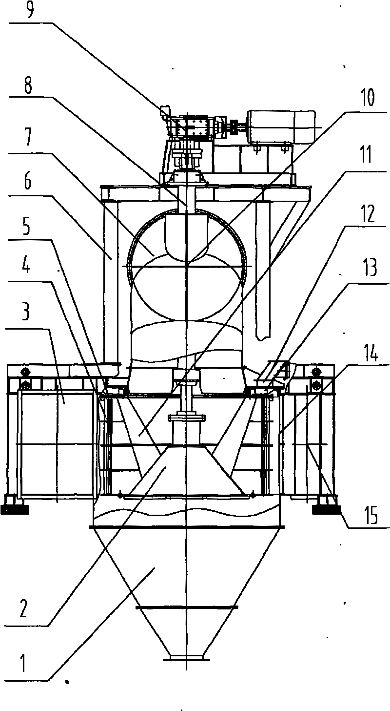
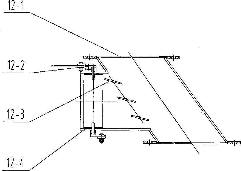
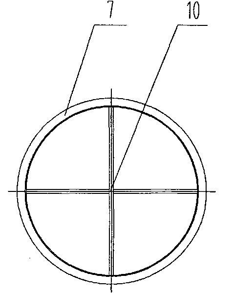
[0029] This specific embodiment includes a cone bucket 1, a cage rotor 2, a primary air inlet 3, a powder selection housing 4, a slope-shaped spreading plate 5, an involute-shaped slope-type spreading plate 5-1, and a baffle plate 5- 2. Rib plate connection device 5-3, bracket 6, air outlet pipe 7, main shaft 8, driving device 9, secondary vortex breaker 10, vortex breaker blade 11, window feed device 12, feed pipe 12 -1. Air inlet regulating valve 12-2, adjustable louver 12-3, square pipe 12-4, equalizing plate 13, air guiding blade 14, secondary air inlet 15.

[0030] The cage rotor 2 is fixed on the main shaft 8 and driven to rotate by the driving device 9; the slope-shaped spreading disc 5 is installed on the upper part of the cage rotor 2 and below the window-type feeding device 12; the cage rotor 2, the main shaft 8, and the slo...


PUM


Abstract

The invention provides a high-efficiency material distribution powder selector which comprises a conical bucket, a cage type rotator, a primary air inlet, a powder selection shell, a slope-shaped material scattering disc, a bracket, an air outlet pipe, a spindle, a drive device, a vortex scattering blade, a window type feeding device, an air guide blade, a secondary air inlet, a secondary vortex scattering device and material distribution plates. The slope-shaped material scattering disc, which consists of an involute type slope-shaped material scattering plate, a material baffle and a reinforcing plate connecting device, is installed at the upper part of the cage type rotator and below the window type feeding device, the window type feeding device comprises a feeding pipe, an air inlet adjustment valve, an adjustable shutter and a square pipe, the square pipe is installed on the side surface of the feeding pipe, the air inlet adjustment valve is installed in the square pipe, an opening is arranged at the joint of the square pipe and the feeding pipe, the adjustable shutter is arranged at the opening part, a set of static material distribution plates is arranged above the material scattering disc, and the vortex scattering device is arranged at the air outlet part of the air outlet pipe.

Description

technical field [0001] The invention relates to powder sorting and grading equipment, in particular to a high-efficiency homogeneous powder separator suitable for separating qualified fine powder from powder after grinding raw materials in industries such as building materials, metallurgy and mining. Background technique [0002] At present, in the domestic building materials, metallurgy, mining and other industries, the powder separation equipment used for raw material grinding is based on the "third-generation high-efficiency powder separator - cage powder separator" as the main body of separation. Compared with the first-generation centrifugal powder separator and the second-generation cyclone separator, the equipment has many advantages such as increasing production, saving energy, and improving quality, but it also has the following defects: [0003] 1. Since the airflow flowing into the rotor blade is blocked by the bottom of the spreading plate, and the rest has no pl...

Claims


Application Information

Patent Timeline
IPC IPC(8): B07B4/06B07B11/06
Inventor 耿桂淦吉文清何美华袁海燕
Owner JIANGSU KEHANG ENVIRONMENT ENG TECH
Learn More