
Variable timing system oil-way of minicar engine cylinder body assembly

A technology for engine cylinders and microcars, applied to engine components, machines/engines, mechanical equipment, etc., can solve problems such as pressure oil leakage, complex process, and large chain motion noise, and achieve reduced starting noise, reduced motion noise, The effect of simple manufacturing process

Active Publication Date: 2010-06-02
LIUZHOU WULING LIUJI POWER
View PDF1 Cites 9 Cited by
  • Summary
  • Abstract
  • Description
  • Claims
  • Application Information

AI Technical Summary

Problems solved by technology

[0002] "VVT" is the English abbreviation of the variable valve timing system of the engine. The number of parts is large, the structure is not compact, the volume is large, and the process is complicated; at present, the authorized announcement number is: CN100532814C The invention patent discloses a technology of casting the VVT ​​oil circuit on the camshaft bearing cap of the automobile engine, although it has the technology Simple, compact structure, which greatly reduces the space occupied by the cylinder head on the entire engine and the weight of the whole machine. The seal of the oil circuit is unreliable, prone to pressure oil leakage and oil leakage, which affects the use effect
In addition, the distance between the supplementary oil passage of the hydraulic tensioner and the main oil passage is long, and the hydraulic tensioner cannot replenish lubricating oil in time, resulting in loud chain movement noise and loud engine starting noise

Method used


Image

  • Variable timing system oil-way of minicar engine cylinder body assembly
  • Variable timing system oil-way of minicar engine cylinder body assembly
  • Variable timing system oil-way of minicar engine cylinder body assembly

Examples


Embodiment Construction

[0028] The utility model relates to an oil circuit of a variable timing system of a microcar engine block assembly.

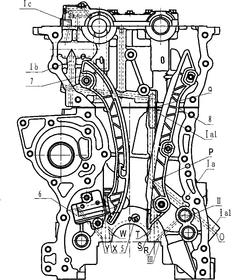
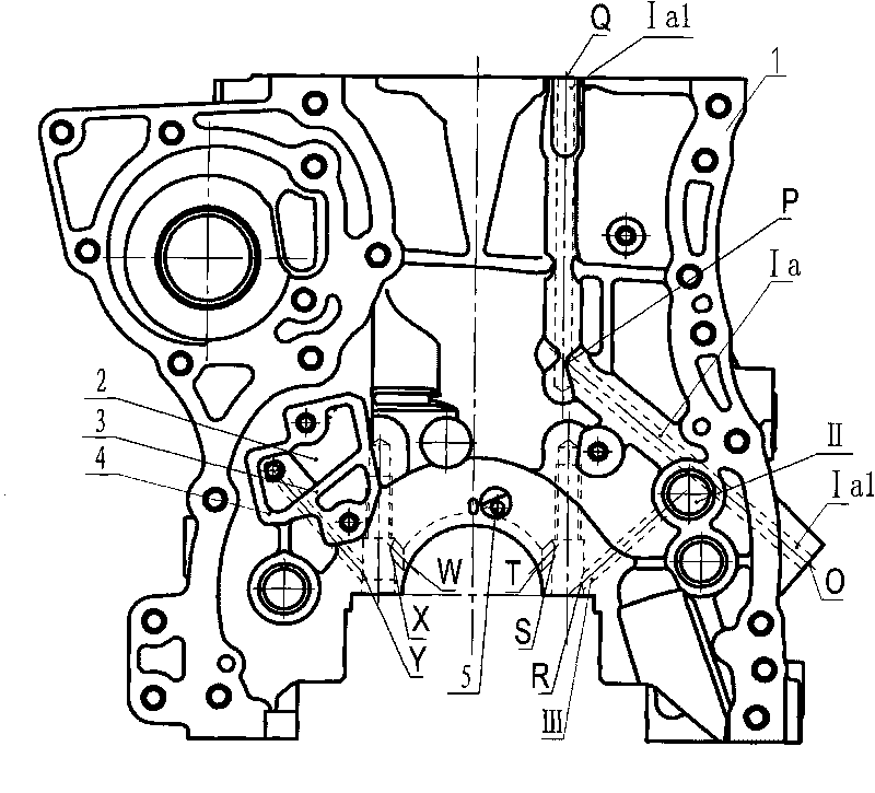
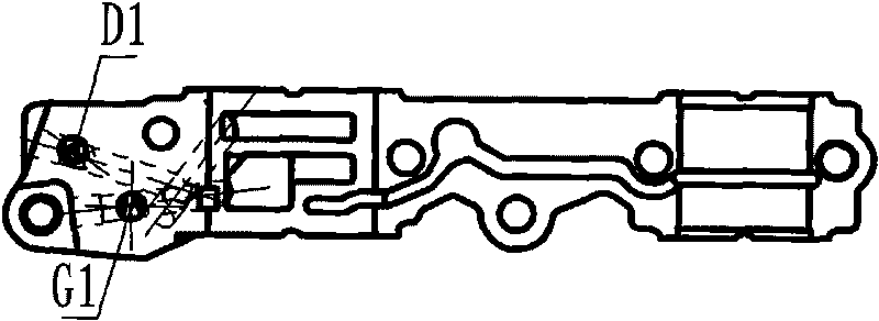
[0029] Such as figure 1 As shown, the variable timing system oil circuit of the microcar engine block assembly includes a VVT oil circuit and a hydraulic tensioner oil circuit, and the VVT ​​oil circuit includes a VVT oil circuit built in the cylinder body Ia and the VVT ​​oil passage Ib built in the cylinder head body and the VVT ​​oil passage Ic located in the first camshaft bearing cap, the VVT ​​oil passage I built in the cylinder body is connected by the main oil passage II and the points O and P The VVT ​​oil passage Ia1 of the cylinder body between point Q and point Q is formed, and at point Q it communicates with the VVT ​​oil passage Ib built in the cylinder head body, and the direction of the oil passage is: main oil passage II → point P → point Q; The hydraulic tensioner oil passage III is composed of the main oil passage II and the oil passage conn...


PUM


Abstract

The invention discloses a variable timing system oil-way of a minicar engine cylinder body assembly, comprising a VVT oil-way and a hydraulic tensioner oil-way. The VVT oil-way comprises a VVT oil-way placed in the main body of the cylinder body, a VVT oil-way placed in the main body of a cylinder cover and a VVT oil-way located in a first camshaft bearing cover; the pressure oil and the lubricating oil supplied to the VVT enter the main body of the cylinder cover through the main body of the cylinder body through the Q point and are divided into two paths through the B point; after the B-C oil-way driving the VVT passes an oil pressure control valve, the B-C oil-way is divided into a VVT advance angle control oil-way and a VVT lag angle control oil-way, the pressure oil of the two oil-ways respectively enters the lag angle control oil-way and the advance angle control oil-way in the first camshaft bearing cover matched with the main body of the cylinder cover to control a VVT regulating gas inlet phase. The variable timing system oil-way has reliable sealing, the pressure oil leakage and mixing phenomenon does not occur; and the distance between the supplementation oil-way of the hydraulic tensioner and the main oil-way is relatively short, the hydraulic tensioner can supplement the lubricating oil in time, and the motion noise of the chains is greatly reduced.

Description

【Technical field】 [0001] The invention relates to an automobile engine accessory, in particular to an oil circuit of a variable timing system of a miniature automobile engine cylinder block assembly. 【Background technique】 [0002] "VVT" is the English abbreviation of the variable valve timing system of the engine. The number of parts is large, the structure is not compact, the volume is large, and the process is complicated; at present, the authorized announcement number is: CN100532814C The invention patent discloses a technology of casting the VVT ​​oil circuit on the camshaft bearing cap of the automobile engine, although it has the technology Simple, compact structure, which greatly reduces the space occupied by the cylinder head on the entire engine and the weight of the whole machine. The seal of the oil circuit is unreliable, prone to pressure oil leakage and oil leakage, which affects the use effect. In addition, the distance between the supplementary oil passage ...

Claims


Application Information

Patent Timeline
Patent Type & Authority Applications(China)
IPC IPC(8): F01M9/10F01L1/34
Inventor 姚克甫廖振华秦际武杨桂兰李兵朱柳坤
Owner LIUZHOU WULING LIUJI POWER
Learn More