Staggered positioning combination piston ring

A combined piston and staggered technology, applied in the field of piston rings, can solve problems such as engine power drop, engine damage, and increased fuel and lubricating oil consumption.

Inactive Publication Date: 2010-06-02
雷义才
View PDF0 Cites 1 Cited by
  • Summary
  • Abstract
  • Description
  • Claims
  • Application Information

AI Technical Summary

Problems solved by technology

[0002] Due to the inherent defects of the existing piston internal combustion engine piston ring, in addition, during use, the opening caused by wear and tear increases, the wall pressure of the piston ring decreases, and the sealing of the opening end, side, an...

Method used


Image

  • Staggered positioning combination piston ring
  • Staggered positioning combination piston ring
  • Staggered positioning combination piston ring

Examples


Embodiment 1

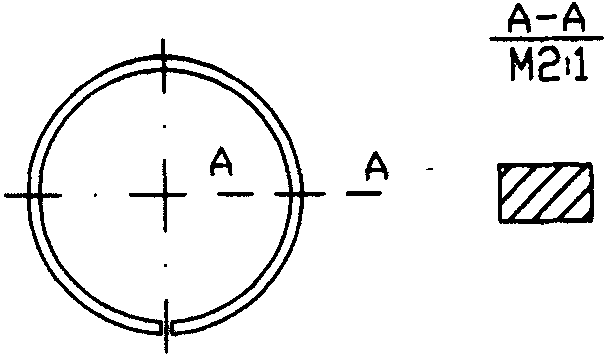
[0018] Embodiment 1 Staggered positioning combined gas ring, the main ring is a rectangular gas ring, and the secondary ring is a steel ring, see Image 6 . Replace the existing rectangular air ring ( figure 1 ) Process a stepped ring groove on the outer side of the rectangular ring according to the design requirements, drill a small hole close to the inner circular surface of the step at about 30° on the stepped ring groove surface as shown in the figure, install the pin, and then place the steel sheet ring( Figure 5 ) Align the arc notches at both ends of the opening with the pins and assemble. When using and installing, the stepped ring groove and the steel sheet ring are on the lower side of the piston gas ring groove.

Embodiment 2

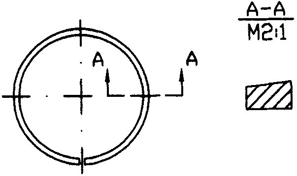
[0019] Embodiment 2 Staggered positioning combination gas ring, the main ring is a wedge-shaped gas ring, and the secondary ring is a steel ring, see Figure 7 . Insert the existing wedge-shaped gas ring ( figure 2 ) Process a stepped ring groove on the outside of the wedge-shaped ring plane according to the design requirements, and the rest are the same as in embodiment 1.

Embodiment 3

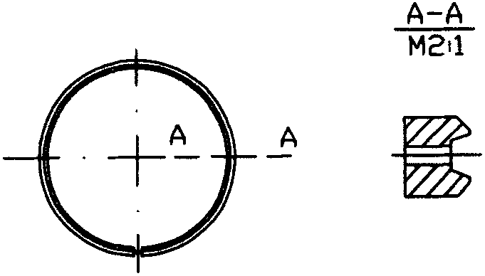
[0020] Embodiment 3 Staggered positioning combined oil ring, the main ring is a spiral spring oil ring, and the secondary ring is a steel sheet ring, see Figure 8 . Put the current spiral support spring oil ring body ( Figure 4 ) According to the design requirements, a stepped ring groove is processed on the outer surface of the ring body. On the solid part of the stepped ring groove surface at 25°-50° as shown in the figure, a small hole is drilled close to the inner circular surface of the step, and installed Pin, and then the steel ring ( Figure 5 ) Align the arc notches at both ends of the opening with the pins and assemble. When using and installing, the stepped ring groove and the steel sheet ring are on the upper side of the piston oil ring groove.

[0021] The advantages of staggered positioning combined piston rings are:

[0022] 1. The technology is novel, the structure is unique, the design is scientific, and it is the first at home and abroad.

[0023] 2. E...


PUM


Abstract

The invention relates to a staggered positioning combination piston ring which comprises a main ring, a subsidiary ring and a pin, wherein the main ring comprises a gas ring and an oil ring; the gas ring mainly comprises a rectangular ring and a wedge-shaped ring; the oil ring mainly comprises an integral oil ring and a spiral support spring oil ring; the subsidiary ring is a steel sheet ring, installed on a step type annular groove of the main ring , prevents the main ring and the subsidiary ring from relatively rotating circumferentially under the positioning action f the pin to avoid the closed overlapping of the main ring and the subsidiary ring, and an omnibearing sealed system is formed, thereby eliminating gas leakage and oil spray fundamentally. The staggered positioning combination piston ring has good quality, reliability and durability and is a generation of optimal and most valuable green product for saving energy and reducing consumption. The popularization and application of the staggered positioning combination piston ring build a practical and ideal platform for leading the discharge index of an engine to reach the high standard requirement of Europe and America and bring great social and economic benefits. The staggered positioning combination piston ring can be used for an air compressor and other relevant devices.

Description

technical field [0001] The invention relates to a piston ring, in particular to a piston ring of a piston internal combustion engine, an air compressor and other related devices. Background technique [0002] Due to the inherent defects of the existing piston-type internal combustion engine piston ring, in addition, during use, the opening caused by wear and tear increases, the wall pressure of the piston ring decreases, the seal of the opening end, side, and outer circular surface decreases, and air leakage, Oil leakage is becoming more and more serious, resulting in reduced engine power, worsened emissions, sharp increase in fuel and lubricating oil consumption, piston rings and other related parts and even engine damage. Contents of the invention [0003] The object of the present invention is to provide a piston ring with excellent sealing performance and long-lasting effect, so as to solve the serious problems caused by air leakage and oil blow-by in the background te...

Claims


Application Information

Patent Timeline
IPC IPC(8): F16J9/14F02F5/00F04B39/00
Inventor 雷义才
Owner 雷义才
Why Eureka
Try Eureka