Photovoltaic concentrators based on non-imaging optics

A non-imaging optics and concentrator technology, applied in the field of photovoltaic concentrators, which can solve the problems of low concentration multiple, large aspect ratio and high cost

Inactive Publication Date: 2011-12-28
HARBIN INST OF TECH
View PDF0 Cites 0 Cited by
  • Summary
  • Abstract
  • Description
  • Claims
  • Application Information

AI Technical Summary

Problems solved by technology

[0003] In order to solve the problems of high cost and low concentrating multiples of the concentrators with low concentrating multiples in the prior art, and the problems of narrow concentrating angle and too large aspect ratio of the concentrators with high concentrating multiples, the present invention proposes A photovoltaic concentrator based on non-imaging optics

Method used


Image

  • Photovoltaic concentrators based on non-imaging optics
  • Photovoltaic concentrators based on non-imaging optics
  • Photovoltaic concentrators based on non-imaging optics

Examples


specific Embodiment approach 1

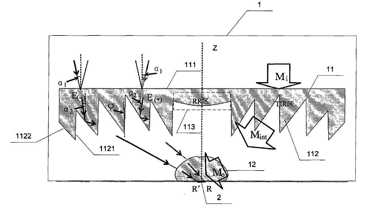
[0034] Specific implementation mode one: combine figure 1 and figure 2Describe this embodiment, the photovoltaic concentrator based on non-imaging optics, it is made up of concentrator 1 and solar cell 2, and described concentrator 1 is made up of main lens 11 and secondary lens 12, and main lens 11 and secondary lens The lens 12 is an axisymmetric structure, the upper surface 111 of the main lens 11 is a plane, and the lower surface of the main lens 11 is divided into two parts, one part is the TIR region, and the other part is the RR region 113, and the RR region 113 is in the TIR region. In the center of the TIR zone, there are N Fresnel teeth 112 in the TIR zone, each Fresnel tooth 112 in the TIR zone is composed of a refraction surface 1121 and a total internal reflection surface 1122, and the refraction of the Fresnel teeth 112 in each TIR zone is The included angle between the surface 1121 and the axis of symmetry of the main lens 11 is The material refractive index...

specific Embodiment approach 2

[0064] Specific embodiment 2: This embodiment is a further description of step 1 in specific embodiment 1: C described in step 1 g =A i / A o is obtained according to the following method: the upper surface 111 of the main lens 11 receives the light beam M i , the gathering angle of the incident ray is a 1 , the light beam M received by the surface of solar cell 2 o , the upper surface 111 receives the light beam M i The boundary ray dM i The angle between each point of the receiving surface and the normal line of the point is a 1 angle of light, the receiving beam M i The light beam refracted by the upper surface 111 is M int , a 2 Beam M int The maximum angle with the z axis, a 2 It is called the inner collecting light angle of the main lens 11, and its calculation formula is:

[0065] sin(a 1 )=n·sin(a 2 )

[0066] In the above formula, n is the material refractive index of the main lens 11 and the secondary lens 12 of the concentrator 1, and the light beam M r...

specific Embodiment approach 3

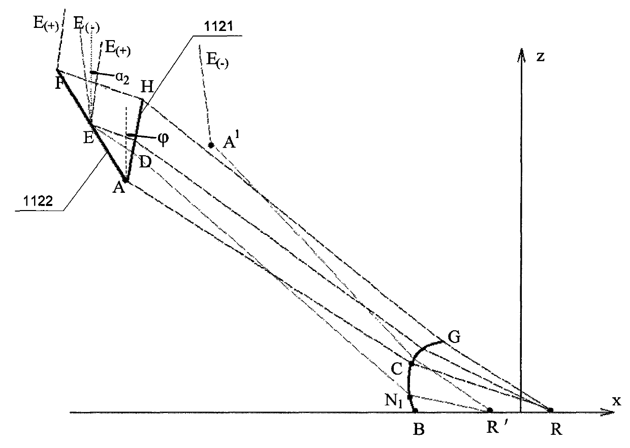
[0081] Specific embodiment three: this embodiment is a further description of step 4 in specific embodiment 1: the coordinates of point A in step 4 are (x A ,z A ), the coordinates of point B are (x B ,z B ), calculate a section of conic curve of the surface boundary of secondary lens 12 according to the coordinates of point A, point B and point R ', described quadratic curve is a Cartesian ellipse, and the curve equation is:

[0082] ( x - x A ) 2 + ( z - z A ) 2 + n · ( x - x ...


PUM


Abstract

The invention relates to a photovoltaic optical collector based on nonimaging optics, belonging to a photovoltaic optical collector and solving the problems of high cost and low optical collection magnification in the optical collector with lower optical collection magnification in the prior art. The photovoltaic optical collector comprises an optical collector and a solar battery, wherein the optical collector comprises a main lens and a secondary lens, the upper surface of the main lens is a plane, the lower surface of the main lens is divided into two parts, one part is TIR region Fresnel teeth and the other part is an RR region, one side of the TIR region Fresnel teeth is provided with a refraction surface and the other side is provided with a total internal reflection surface, an included angle of the refraction surface and a z axis is Phi, and the refractive index of materials made into the main lens and the secondary lens are both n. The optical collector can reach about 1000 times of optical collection magnification, and has height to width aspect ratio of less than 0.5, optical collecting angle of more than 1 degree and optical efficiency of more than 80 percent. The invention is suitable for occasions and fields of photovoltaic optical collectors with higher optical collection magnification.

Description

technical field [0001] The invention relates to a photovoltaic concentrator. Background technique [0002] In a photovoltaic power generation system, the cost of solar cells accounts for a large proportion of the entire system cost. In order to reduce the cost of photovoltaic power generation, the most effective and fast method is to use a concentrator made of plexiglass to gather sunlight to a small solar cell surface. Photovoltaic concentrators currently used in the market can be divided into low-power concentrators (the concentrating factor is less than 100) and high-power concentrators (the concentrating factor is greater than 100) according to the concentrating ratio. The low-power concentrator achieves the purpose of concentrating sunlight through the reflection or refraction of light by optical elements. It can achieve a wide collection angle, but the low-power concentrator still uses a large amount of solar cells per unit area for collecting sunlight. , can not gre...

Claims


Application Information

Patent Timeline
Patent Type & Authority Patents(China)
IPC IPC(8): H01L31/052H01L31/0232G02B3/00H01L31/055
CPCY02E10/52
Inventor 陈俊云赵清亮
Owner HARBIN INST OF TECH
Why Eureka
Try Eureka