High voltage wall bushing

A high-voltage wall-penetrating bushing and set technology, which is applied in the direction of pipes, pipes/pipe joints/pipes, electrical components, etc., can solve the problems of reducing mechanical strength and insulation performance, scratching and discharging, high processing accuracy and difficulty, and achieves improved Bond strength and stability, increase adhesive bond strength, good pressure equalization effect

Active Publication Date: 2012-04-25
高电科技有限公司
View PDF0 Cites 2 Cited by
  • Summary
  • Abstract
  • Description
  • Claims
  • Application Information

AI Technical Summary

Problems solved by technology

This traditional high-voltage bushing has the following disadvantages: (1) After the thread is milled on the outer wall of the inner insulating layer, the mechanical structure of the outer wall is destroyed, and its mechanical strength and insulation performance are reduced. groove, it is very easy to generate corona and cause flash discharge, which will damage the high voltage bushing
(2) Since it is necessary to mill out threads on the outer wall of the inner insulating layer, this process needs to mill off nearly half the length of the groove on the outer wall of the inner insulating layer, and then mill out the outer threads on the remaining outer wall of the inner insulating layer. In this process, it is necessary to mill off more heavy layers, resulting in serious waste. At the same time, this process is time-consuming and laborious, and the processing accuracy and difficulty are high, thereby increasing the manufacturing cost.

Method used


Image

  • High voltage wall bushing
  • High voltage wall bushing
  • High voltage wall bushing

Examples


Embodiment 1

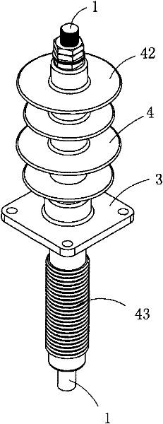
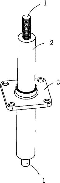
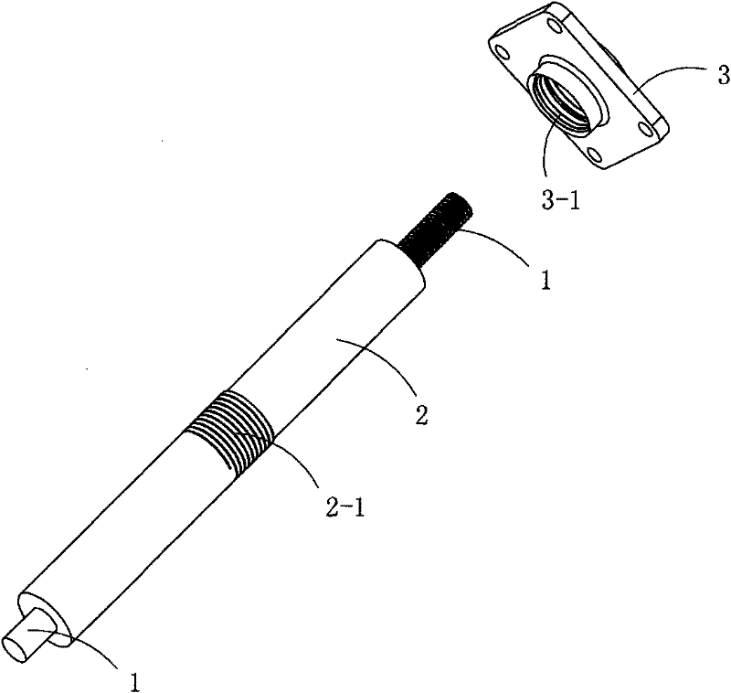
[0032] Figure 4 to Figure 9 A specific embodiment of the invention is shown in which, Figure 4 It is a schematic diagram of a three-dimensional structure of the present invention; Figure 5 yes Figure 4 A schematic diagram of a three-dimensional structure of the high-voltage wall bushing shown after removing the creep-increasing insulating layer; Figure 6 yes Figure 5 The exploded schematic diagram of the high-voltage wall bushing after removing the creep-enhancing insulation layer; Figure 7 yes Figure 4 A schematic diagram of the three-dimensional structure of the connecting flange in the high-pressure wall bushing shown; Figure 8 yes Figure 7 A schematic diagram of the three-dimensional structure of the connecting flange shown when viewed from another angle; Figure 9 yes Figure 7 Half-section view of connecting flange shown.

[0033] This embodiment is a kind of high-voltage wall-through bushing, see Figure 4 to Figure 6 , including a conductive rod 1, ...

Embodiment 2

[0045] This embodiment is basically the same as Embodiment 1, except that: the inner insulating layer 2 is provided with an external thread at the glued joint with the connecting flange 3).

Embodiment 3

[0047] This embodiment is basically the same as Embodiment 1, except that: the inner insulating layer 2 is provided with an annular groove at the glued joint with the connecting flange 3 .


PUM


Abstract

The invention discloses a high voltage wall bushing which comprises an electricity conducting rod, an inner insulation layer surrounding the middle part of the electricity conducting rod, a connecting flange arranged on the inner insulation layer and an increase climbing outer insulation layer sleeved on the inner insulation layer and positioned at both sides of the connecting flange, and the connecting flange is glued and fixed on the outer wall of the inner insulation layer by an adhesive. In the invention, the processing and manufacturing are both convenient, resources are saved, and the cost is low.

Description

technical field [0001] The invention belongs to the technical field of high-voltage electrical appliances, and in particular relates to a high-voltage wall-through bushing. Background technique [0002] In the technical field of high-voltage electrical appliances, the high-voltage wall bushing is a device that passes the high-voltage power supply through the wall and leads it from indoor to outdoor or from indoor to outdoor, or a device for high-voltage switches or transformers to pass through the shell wall inside and outside to guide high-voltage power. [0003] Figure 1 to Figure 3 shows a conventional high voltage wall bushing where figure 1 It is a schematic diagram of a three-dimensional structure of a traditional high-voltage wall bushing; figure 2 yes figure 1 A schematic diagram of a three-dimensional structure of the high-voltage wall bushing shown after removing the creep-increasing insulating layer; image 3 yes figure 2 An exploded schematic diagram of ...

Claims


Application Information

Patent Timeline
Patent Type & Authority Patents(China)
IPC IPC(8): H02G3/22F16L5/00
Inventor 朱桂盛朱晓旺朱晓杰
Owner 高电科技有限公司
Why Eureka
Try Eureka