Seat reclining apparatus

An angle adjustment device and seat technology, applied in vehicle seats, chairs, reclining chairs, etc., can solve problems such as size restrictions, and achieve the effect of suppressing shaking and moving smoothly

Inactive Publication Date: 2010-06-09
FUJI KIKO CO LTD
View PDF1 Cites 5 Cited by
  • Summary
  • Abstract
  • Description
  • Claims
  • Application Information

AI Technical Summary

Problems solved by technology

[0006] However, since both the inner convex portion and the outer convex portion of the seat reclining device described in Patent Document 1 are formed by embossing, they cannot be overlapped and formed on the inner surface of a single circle. Only one of them can be formed at the same position as the outer surface. Therefore, even if the area of ​​the inner convex part is increased to increase the rotational strength, the outer convex part can only reduce the increase of the inner convex part. restricted

Method used


Image

  • Seat reclining apparatus
  • Seat reclining apparatus
  • Seat reclining apparatus

Examples


Embodiment approach 1

[0042] First, according to Figure 1, figure 2 Embodiment 1 will be described.

[0043] (structure)

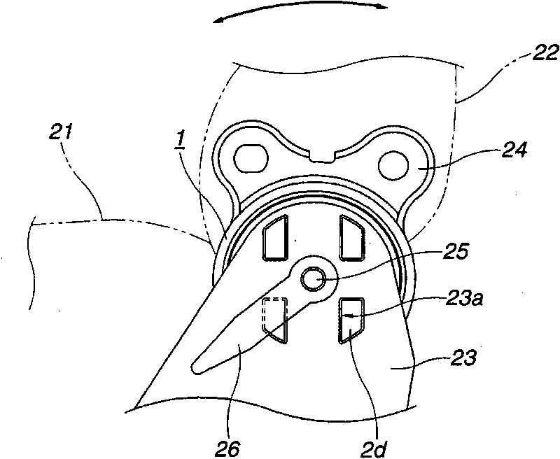
[0044] Set up on the vehicle as figure 2 seat shown. That is, a seat cushion 21 is provided as a portion to sit on, and a seat back 22 is attached so as to be rotatable in the front-rear direction of the vehicle with respect to the seat cushion 21 . The fixed part of the recliner 1 is coupled to the seat cushion 21 via the base plate 23 , while the movable part of the recliner 1 is coupled to the seat back 23 via the arm plate 24 . Furthermore, a spring (not shown) is provided for biasing the seat back 22 so as to tilt the seat back 22 to the left side which is the front of the vehicle with respect to the seat cushion 21 .

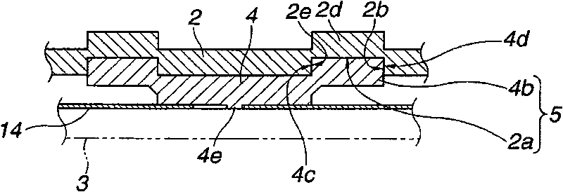
[0045] The structure of the above-mentioned recliner 1 is shown in FIG. 1 . The fixing member 2 constituting the recliner 1 is substantially disc-shaped, and has a circular recess formed inside. On the other hand, the rotating member 3 is rotatably fi...

Embodiment approach 2

[0060] Next, according to image 3 Embodiment 2 will be described. Since a part of Embodiment 1 is changed in this embodiment, the same reference numerals are assigned to the same parts and description thereof will be omitted, and only different parts will be described.

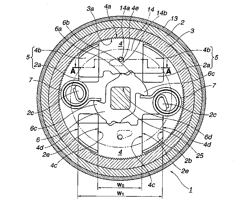
[0061] As shown in the figure, the pair of guide protrusions 4b are integrally provided at the outer teeth forming portion (W) of the locking teeth 4. 0 part of the inside). Therefore, the full width W of the locking tooth 4 2 and the tooth width dimension W of the external tooth 4a 0 the same, W 2 =W 0 .

[0062] According to the present invention, since the pair of guide protrusions 4b are provided inside the outer teeth forming portion of the lock teeth 4, the circumferential width (W) of the lock teeth 4 can be reduced. 2), when the locking teeth 4 are arranged on the fixing member 2 along the circumferential direction, the angle occupied by the locking teeth 4 in the circumferential direction is r...

Embodiment approach 3

[0066] Next, according to Figure 4 Embodiment 3 will be described. Since a part of Embodiment 2 is changed in this embodiment, the same reference numerals are assigned to the same parts and descriptions thereof are omitted, and only different parts will be described.

[0067] Embodiment 3 is the same as Embodiment 2, and the full width W of the locking teeth 4 2 Equal to the tooth width dimension W of the external tooth 4a 0 , that is, make W 2 =W 0 . Furthermore, three lock teeth 4 are equally arranged along the circumferential direction.

[0068] Due to the full width W of the locking tooth 4 2 Therefore, even if the coil spring 7 is arranged between the lock teeth 4, three lock teeth 4 can be evenly arranged along the circumferential direction. Due to the increased number of locking teeth 4, the rotational strength of the recliner 1 is greatly improved.

[0069] Since other structures and functions are the same as those in Embodiment 2, description thereof will be ...


PUM


Abstract

A seat reclining apparatus includes: a fixing member; a pivot member having an internal tooth located on an inner circumference surface of the circular recessed portion; a lock tooth having an external tooth arranged to be engaged with the internal tooth of the pivot member, the lock tooth being arranged to be moved along an orbit between an engagement position and a disengagement position; a cam; an urging member; the lock tooth including a pair of guide protrusions which are disposed on both sides of the lock tooth, and which protrude axially toward the fixing member, and the fixing member including a pair of guide grooves formed on an inside surface of the fixing member, and arranged to receive, respectively, the guide protrusions of the lock tooth to guide the lock tooth along the orbit between the engagement position and the disengagement position.

Description

technical field [0001] The present invention relates to a device that does not decrease the rotational strength even if the outer diameter size is reduced by increasing the rotational strength of a seat reclining device. Background technique [0002] A seat reclining device for a vehicle is configured by providing a recliner between a seat cushion and a seat back that rotates relative to the seat cushion. That is, the cushion side arm provided on the seat cushion and the backrest side arm provided on the seat back are relatively rotatably connected via a recliner. [0003] In order to miniaturize the seat cushion and the seat back, there is a demand to reduce the width dimension of the cushion side arm and the backrest side arm, and therefore, the outer diameter dimension of the recliner needs to be reduced. On the other hand, even if the outer diameter is reduced, the strength for restricting the rotation must be maintained at the same level as in the past, and the strengt...

Claims


Application Information

Patent Timeline
Patent Type & Authority Applications(China)
IPC IPC(8): A47C1/025
CPCB60N2/2356B60N2/236B60N2/2362
Inventor 大庭彻也
Owner FUJI KIKO CO LTD
Why Eureka
Try Eureka