
High-precision stamping mould

A stamping die, high-precision technology, applied in the field of tooling and fixtures, can solve the problems of unsatisfactory cooperation accuracy of airport sliders, limit the use efficiency of ordinary punching machines, and the normal use of molds, etc., to achieve reduced processing costs, reasonable structure, and easy operation Effect

Inactive Publication Date: 2010-06-09
MAANSHAN CHENXING MACHINERY MFG
View PDF0 Cites 6 Cited by
  • Summary
  • Abstract
  • Description
  • Claims
  • Application Information

AI Technical Summary

Problems solved by technology

However, the size of the sheet metal workpieces that are often processed is relatively large, and the feeding and movement of the sheet metal parts cannot be hindered. It is required that the mold adopts an open mold without guidance. The orientation and guiding accuracy of the machine tool are also completely guaranteed by the matching accuracy of the machine tool slide block.
However, for the blanking process that requires high guiding precision, such as small gaps and porous combined holes, the matching accuracy of the airport slider is basically not satisfactory, which will cause the phenomenon of mold cutting edge and punch breaking.
The mold cannot be used normally
This severely limits the efficiency of this common punch

Method used


Image

  • High-precision stamping mould
  • High-precision stamping mould

Examples


Embodiment Construction

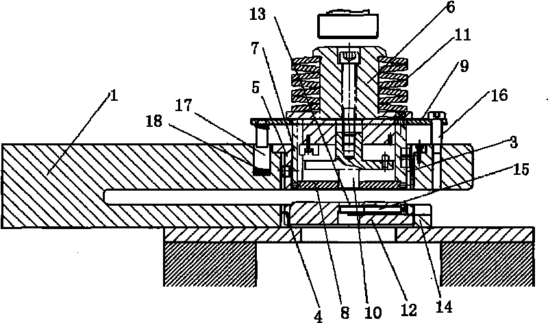
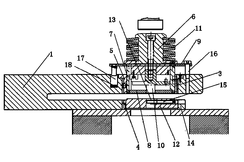
[0011] Referring to the accompanying drawings, the high-precision stamping die includes a mold frame body 1, a lateral blind feeding groove 2 is opened on one side of the mold frame body 1, an upper mold installation hole 3 is opened above the blind feeding groove 2, and a lower mold mounting hole is opened below the blind feeding groove 2. Die mounting hole 4, upper die mounting hole 3 is equipped with a guide die set 5, a pressing device is slidably installed in the guide die set 5, and the pressing device includes a sliding sleeve 7 and a pressing plate 8 at the lower end of the sliding sleeve. The upper end of 7 is equipped with upper formwork 9, is provided with punch 10 in the sliding sleeve, the lower end of punch passes through binder plate 8, the upper end passes through upper formwork and strike column 6 is installed, the top of strike column 6 has steps, strikes A compression spring 11 is set on the column 6, and the lower end of the compression spring is placed on t...


PUM


Abstract

The invention discloses a high-precision stamping mould, comprising a mould frame body, wherein, one side of the mould frame body is provided with a transverse feeding blind groove the upper part of which is provided with an upper die installation hole, and the lower part thereof is provided with a lower die installation hole; a guide die sleeve is arranged in the upper die installation hole; a material pressing device is arranged in the guide die sleeve in a sliding manner; the upper end of a sliding sleeve is provided with an upper die plate; a punch head is arranged in the sliding sleeve; the lower end of the punch head penetrates through the material pressing plate; the upper end of the punch head penetrates through the upper die plate and is provided with a strike post the top of which is provided with steps; a compression spring is sheathed on the strike post; the lower die is arranged in the lower die installation hole; and the lower die is provided with a die cavity matched with the punch head. The high-precision stamping mould of the invention can meet the requirements of stamping clearance of an open mould being smaller than 0.1, centering, orientation and guiding precision in high-precision stamping process of porous combination punching and the like, commonly uses a numerical control turret punch press mould, and ensures normal operation of the mould high-precisionstamping process, and the operation is simple.

Description

technical field [0001] The invention belongs to the field of fixtures, in particular to a high-precision stamping die. Background technique [0002] Now some small and medium-sized sheet metal enterprises often use a common punching machine with an automatic feeder to match different molds for punching, forming and other different cold stamping parts. This kind of equipment is economical and applicable. Especially for the stamping process that can be completed by a single mold, the function of CNC punching machine can be realized. However, the size of the sheet metal workpieces that are often processed is relatively large, and the feeding and movement of the sheet metal parts cannot be hindered. It is required that the mold adopts an open mold without guidance. The orientation and guiding accuracy of the machine tool are also completely guaranteed by the matching accuracy of the machine tool slider. However, for the punching process that requires high guiding precision, su...

Claims


Application Information

Patent Timeline
Patent Type & Authority Applications(China)
IPC IPC(8): B21D37/10B21D37/12
Inventor 陈涉玲
Owner MAANSHAN CHENXING MACHINERY MFG
Learn More