Friction stir spot welding method

A friction stir and spot welding technology, which is applied in the field of friction stir spot welding between metal materials, can solve the problems of excessive surface extrusion, reduce the workload of processing, and weld pressure into the pit depth, etc., to achieve increased heat production, The effect of improving productivity

Inactive Publication Date: 2010-06-09
HUBEI UNIV OF TECH
View PDF0 Cites 17 Cited by
  • Summary
  • Abstract
  • Description
  • Claims
  • Application Information

AI Technical Summary

Problems solved by technology

[0003] Aiming at the problems in the existing methods of pressing deep into the pit after welding and having many extrudates on the surface, the present invention proposes a friction stir spot welding method to solve the shortcomings of deep pressing into the pit and many extrudates in friction stir spot welding , which greatly reduces the workload of subsequent processing

Method used


Image

  • Friction stir spot welding method
  • Friction stir spot welding method

Examples


Embodiment Construction

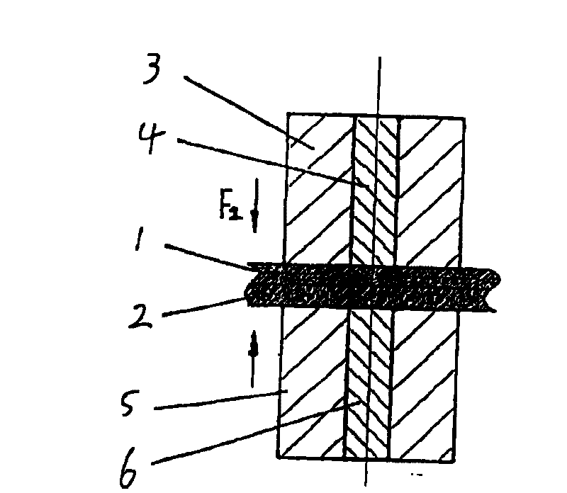
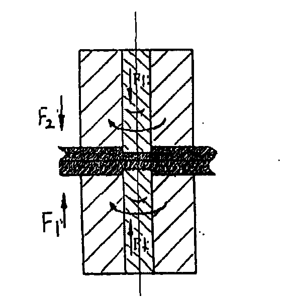
[0008] In the present invention, the upper and lower shaft shoulders and the upper and lower stirring heads are simultaneously rotated and pressurized by the upper and lower shaft shoulders and the stirring heads, so that the welded parts are welded under the action of mechanical friction heat to form high-quality welds. point.

[0009] like figure 1 As shown, 1 and 2 are parts to be welded, 3 is the upper shoulder, 4 is the upper stirring head, 5 is the lower shoulder, and 6 is the lower stirring head. Depend on figure 1 The equipment parameters shown in the schematic diagram of the double-sided friction stir spot welding welding process include: pressure F 1 , F 2 ; Rotation speed of shaft shoulder 3, 5 ω1; Rotation speed of stirring head 4, 6 ω2, and horizontal moving speed V; Stirring head 4, 6 and shaft shoulder 3, 5 up and down movement stroke S; Insertion depth h of stirring head 4, 6 , insertion speed v1, insertion residence time t, withdrawal speed v2 of the stirr...


PUM


Abstract

The invention discloses a friction stir spot welding method. The processing of the friction stir spot welding is synchronously carried out at two surfaces by using a stirring head; a welding part mainly comprises four parts which are an upper stirring head, a lower stirring head, an upper shaft shoulder and a lower shaft shoulder; the frictional heat and the plastic deformation energy in the two-surface friction stir spot welding process are generated from the upper and lower surfaces; the shaft shoulders capable of freely rotating are arranged at periphery of the upper stirring head and the lower stirring head in the two-surface friction stir spot welding technology, and the rotating shaft shoulders can supplement the heat which is not adequately generated by the stirring head in the two-surface friction stir spot welding process. Just because of these differences, the number of pressing pits welding the surfaces and extrudates can be reduced by half and the heat production in the welding process is doubled, thus the two-surface friction stir welding can overcome the defect of the single-surface friction stir spot welding and can improve the productivity.

Description

technical field [0001] The invention relates to a new metal material connection method, especially a friction stir spot welding method between metal materials. Background technique [0002] With the development of the automobile industry, various non-ferrous metal materials have gradually been applied in the automobile manufacturing industry, but the poor weldability of non-ferrous metals limits the application of non-ferrous metals in the field of automobile manufacturing. Friction Stir Welding (FSW), a solid-state joining method proposed by The Welding Institute (TWI for short) in 1991, has a simple principle, few control parameters, easy automation, and no radiation , Can minimize the human factor in the welding process. This method is a low-temperature solid-phase joining method that does not produce metal melting during the welding process. It is suitable for low-melting point alloys that are difficult to weld by fusion welding. At present, all countries are competing ...

Claims


Application Information

Patent Timeline
Patent Type & Authority Applications(China)
IPC IPC(8): B23K20/12
Inventor 董仕节
Owner HUBEI UNIV OF TECH
Why Eureka
Try Eureka