Supercharge Your Innovation With Domain-Expert AI Agents!

Optical path device of numeral control laser cutting machine

A digitally controlled laser and cutting machine technology, applied in laser welding equipment, optics, installation, etc., can solve problems such as difficult application, high cost, and complex structure

Inactive Publication Date: 2010-06-09
江苏扬力数控机床有限公司
View PDF0 Cites 5 Cited by
  • Summary
  • Abstract
  • Description
  • Claims
  • Application Information

AI Technical Summary

Problems solved by technology

[0009] The above three methods are complex in structure, difficult to apply, and extremely expensive

Method used


Image

  • Optical path device of numeral control laser cutting machine
  • Optical path device of numeral control laser cutting machine
  • Optical path device of numeral control laser cutting machine

Examples


Embodiment Construction

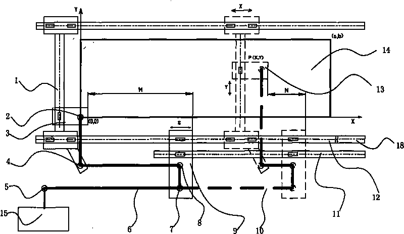
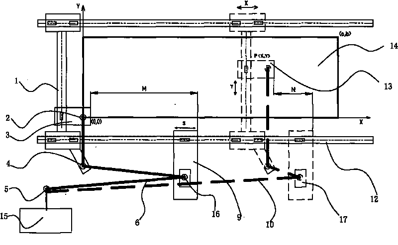
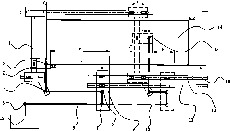
[0026] The present invention as figure 2 As shown, it includes a laser generator 15, a cutting head 2 that uses a lens to form a cutting laser spot on the surface of a workpiece, a conductive optical path device that connects the laser generator 15 and the cutting head 2, and a controller. It is also provided with an equal optical path device, etc. The optical path device includes a trolley 9 driven by a servo motor, at least one compensation mirror 16 arranged on the trolley 9 , and a Y-direction reciprocating mechanism 17 for the compensation mirror 16 . The servo motor is connected to the controller, and the compensating mirror 16 is set in the transmission light path in a meandering manner, and the transmission reflection mirror 5 and the reception reflection mirror 4 are arranged in the transmission light path. Dolly 9 is connected on the beam track 12.

[0027] The controller includes a memory storing a program for moving the optical path device according to the positi...


PUM


Abstract

The invention discloses an optical path device of a numeral control laser cutting machine, which relates to the numeral control laser cutting machine. The optical path device comprises a laser generator, a cutting head for focusing laser with a lens, a conduction optical path for connecting the laser generator with the cutting head and a controller. The optical path device is characterized by being further provided with an aplanatic device, wherein the aplanatic device comprises a trolley driven by a servo motor and at least one compensating reflecting mirror arranged on the trolley; the servo motor is connected with the controller; the compensating reflecting mirror is arranged in the conduction optical path in a zigzagging way; and an emission reflecting mirror and a receiving reflecting mirror matched with the conduction optical path are arranged in the conduction optical path. The aplanatic device of the optical path device is controlled by the controller; and the controller calculates the amount of movement for which the aplanatic device needs to move in a direction S according to a program with functional relationship stored in the controller when detecting the cutting head moves relative to an original position, so that the length of the optical path from the laser generator to the cutting head is consistent when the cutting head is at any point between (0, 0) and (a, b).

Description

technical field [0001] The invention relates to a numerically controlled laser cutting machine, in particular to the design and improvement of the optical path device of the numerically controlled laser cutting machine. Background technique [0002] During the cutting process of the laser cutting machine, the laser beam is focused into a small light spot, so that the focus can reach a high power density. At this time, the heat input by the beam far exceeds the part reflected, conducted or diffused by the material, and the material is quickly heated to the melting and vaporizing temperature. At the same time, a high-speed airflow will melt and vaporize from the coaxial or non-coaxial The material is blown out from the lower part of the material. As the beam moves relative to the material, the hole forms a narrow slit to divide the material. [0003] At present, due to cost reasons, laser generators for civilian use emit laser beams with a certain divergence angle, which mak...

Claims


Application Information

Patent Timeline
Patent Type & Authority Applications(China)
IPC IPC(8): B23K26/38B23K26/08G02B7/182G02B17/06B23K26/064
Inventor 周鹏飞胡金龙洪超翟东升耿天顺
Owner 江苏扬力数控机床有限公司
Features
  • R&D
  • Intellectual Property
  • Life Sciences
  • Materials
  • Tech Scout
  • Unparalleled Data Quality
  • Higher Quality Content
  • 60% Fewer Hallucinations
Learn More