
Electro-hydraulic servo valve

An electro-hydraulic servo valve and valve core technology, applied in the field of servo valves, can solve the problems of poor sealing performance and poor dirt holding capacity, and achieve the effects of convenient installation, less heat generation, and low pressure

Inactive Publication Date: 2010-06-09
SHANGHAI NUOMA HYDRAULIC SYST
View PDF9 Cites 9 Cited by
  • Summary
  • Abstract
  • Description
  • Claims
  • Application Information

AI Technical Summary

Problems solved by technology

[0003] Existing electro-hydraulic servo valve: 1. The general rated pressure is 7-14MPa, the flow rate is 4-300L / min, and there is no low-pressure large-flow (or small-flow) electro-hydraulic servo valve on the market; 2. The ball head of the baffle feedback rod is installed In the center of the valve core; 3. Most of the filters are flat-plate type, with weak dirt-containing ability and poor sealing performance

Method used


Image

  • Electro-hydraulic servo valve
  • Electro-hydraulic servo valve
  • Electro-hydraulic servo valve

Examples


Embodiment 1

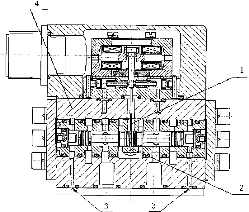
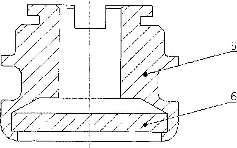
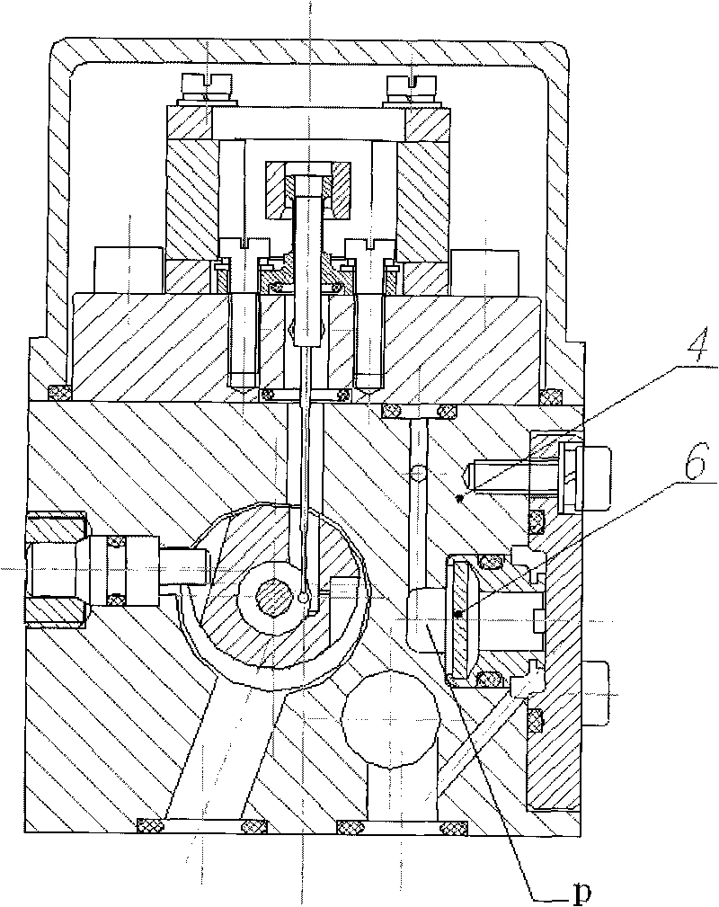
[0017] An electro-hydraulic servo valve, including a combined baffle feedback rod 1, a valve core 2, a pre-stage test hole 3, a filter housing 5 and a filter 6, the valve core 2 is located in the center of the inner cavity of the valve body 4, and the combined The type baffle feedback rod 1 runs through the middle and upper part of the valve body 4, and its lower end ball head is located at the eccentric position of the valve core 2, and the filter 6 is rolled on the lower part of the inner cavity of the filter housing 5.

[0018] The combined baffle feedback rod 1 is made of elastic alloy wire, the valve core 2 is made of tool steel, the filter housing 5 is made of brass, the filter 6 is made of stainless steel wire, and the valve body 4 is made of forged aluminum.


PUM


Abstract

The invention relates to an electro-hydraulic servo valve, which comprises a combined baffle feedback rod (1), a valve core (2), a prestage test hole (3), a filter shell (5) and a filter (6). The electro-hydraulic servo valve is characterized in that: the valve core (2) is positioned at a middle position in an inner cavity of a valve body (4); the combined baffle feedback rod (1) penetrates an upper middle part of the valve body (4), and a ball head at the lower end of the valve body (4) is positioned at an eccentric position of the valve core (2); the filter (6) is rolled inside the filter shell (5); and the filter shell (5) is arranged at the oil inlet (P) of the valve body. The electro-hydraulic servo valve has the characteristics of compact structure, small volume, convenient installation, low pressure, high flow, small internal leakage, less system heat and high frequency response.

Description

technical field [0001] The invention belongs to the field of servo valves, in particular to an electro-hydraulic servo valve. Background technique [0002] The electro-hydraulic servo valve currently used in the electro-hydraulic control system has the following defects: [0003] Existing electro-hydraulic servo valve: 1. The general rated pressure is 7-14MPa, the flow rate is 4-300L / min, and there is no low-pressure large-flow (or small-flow) electro-hydraulic servo valve on the market; 2. The ball head of the baffle feedback rod is installed In the center of the valve core; 3. Most of the filters are flat-plate type, with weak dirt-containing ability and poor sealing performance. Contents of the invention [0004] The technical problem to be solved by the present invention is to provide an electro-hydraulic servo valve, which has the characteristics of small volume, low pressure, large flow rate, small internal leakage, low system heat generation and high frequency resp...

Claims


Application Information

Patent Timeline
Patent Type & Authority Applications(China)
IPC IPC(8): F15B13/02
Inventor 刘明刘月华
Owner SHANGHAI NUOMA HYDRAULIC SYST
Learn More