
Multidirectional rotating platform

A rotating platform, multi-directional technology, applied in the direction of machine/support, optics, instruments, etc., can solve the problems of complex drive system structure, susceptibility to electromagnetic interference, high cost, etc., and achieve the effect of small size, low cost and simple structure

Active Publication Date: 2010-06-09
JOHNSON ELECTRIC SHENZHEN
View PDF1 Cites 7 Cited by
  • Summary
  • Abstract
  • Description
  • Claims
  • Application Information

AI Technical Summary

Problems solved by technology

[0004] However, the above-mentioned traditional drive systems are complex in structure, high in cost, large in size, and susceptible to electromagnetic interference

Method used


Image

  • Multidirectional rotating platform
  • Multidirectional rotating platform
  • Multidirectional rotating platform

Examples


Embodiment Construction

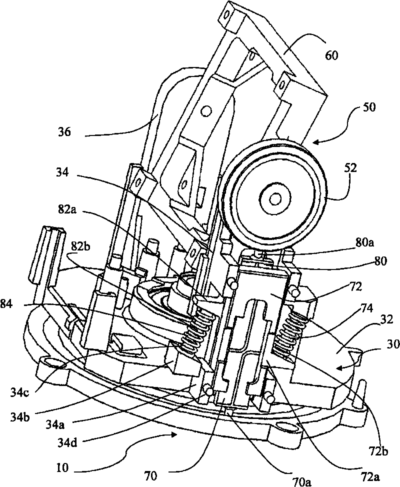
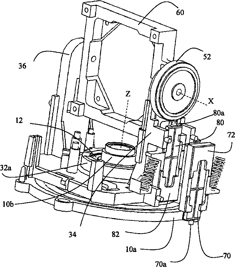
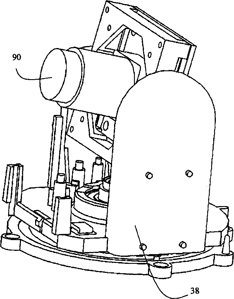
[0016] See figure 1 versus figure 2 A multi-directional rotating platform according to an embodiment of the present invention includes a base 10, a first platform 30, and a second platform 50.

[0017] The base 10 includes a disc-shaped body 10a and a shaft 10b extending perpendicularly from a central position on one side of the disc-shaped body 10a.

[0018] The first platform 30 includes a base plate 32 and two supporting seats 34 and 36 extending upward from two opposite sides of the base plate 32. A mounting portion 32 a with a hollow structure is provided in the center of the base plate 32, and the shaft 10 b of the base 10 is mounted in the mounting portion 32 a of the base plate 32 through a bearing 12.

[0019] The second platform 50 includes a rotating body such as a turntable 52. The turntable 52 is rotatably mounted on one of the support seats 34 of the first platform 30 through a rotating shaft, and a mounting seat 60 is mounted on the first platform 30. Between the two...


PUM


Abstract

The invention provides a multidirectional rotating platform, comprising a base, a first platform which is installed on the base and can rotate along a first axis relative to the base and a second platform which is installed on the first platform and can rotate along a second axis relative to the first platform. The rotating platform is characterized in that the rotating platform also comprises two piezo motors which are installed on the first platform, wherein one piezo motor is used for driving the first platform and the second platform to rotate relative to the base, and the other piezo motor is used for driving the second platform to rotate relative to the first platform. The multidirectional rotating platform has simple structure, small volume and low cost and is less affected by electromagnetic interference. The invention also provides a multidirectional camera system applying the multidirectional rotating platform.

Description

Technical field [0001] The invention relates to a multi-directional rotating platform. Background technique [0002] The multi-directional camera system can be used to control the multi-directional rotating platform so that the lens can capture the scene in any direction, so its application is becoming more and more extensive. For example, it can be used in surveillance and / or alarm systems, as well as in robot vision, etc. . [0003] Generally, these systems include electromagnetic motors connected to the camera through a relatively complex transmission system. The motor and transmission system are controllable to position the optical axis of the camera in a relatively wide range of directions so that the camera can image sufficiently larger than the camera's vision. The scene in the extended field of view. In addition, some people use multiple stepper motors to control the movement of different platforms. [0004] However, the above-mentioned traditional driving system has compl...

Claims


Application Information

Patent Timeline
Patent Type & Authority Applications(China)
IPC IPC(8): F16M11/06G03B17/56
Inventor 杨小军艾力.阿巴杜潘广业关伟伦曾凡春
Owner JOHNSON ELECTRIC SHENZHEN
Learn More