Lighting lens and lighting device equipped with the same
A technology of lens and light-emitting device, which is applied in the direction of lighting devices, components of lighting devices, lighting and heating equipment, etc., and can solve problems such as difficulty in suppressing uneven color of the illuminated surface, poor light utilization efficiency, etc.
- Summary
- Abstract
- Description
- Claims
- Application Information
AI Technical Summary
Problems solved by technology
Method used
Image

Examples
Embodiment approach 1
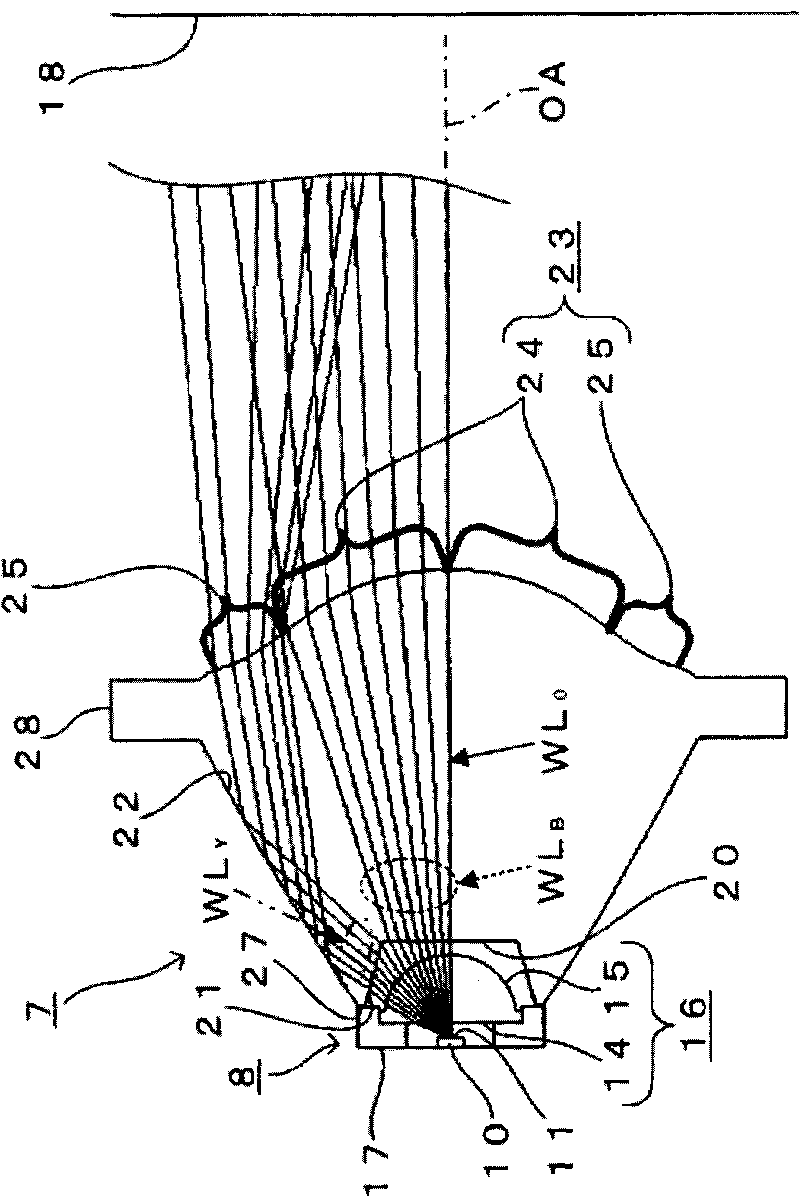
[0050] Below, refer to Figure 2 to Figure 5 An embodiment of a spotlighting lens used in a spotlighting device as an illumination lens of the present invention will be described.
[0051] In addition, the same code|symbol is used for the part whose basic structure is the same as conventional or similar to this, and is demonstrated.
[0052] Such as figure 2 As shown, the spotlighting lens 7 of this embodiment is arranged opposite to the white light emitting diode 8 as a point light emitting device emitting white light, and together with the white light emitting diode 8 constitutes a spotlighting device.
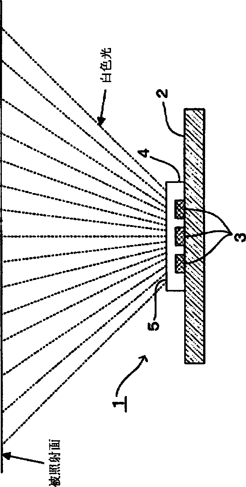
[0053] In addition, the white light-emitting diode 8 in this embodiment has a light-emitting unit 10 that is, for example, compatible with figure 1 The structure shown is similarly composed of a combination of a light-emitting element of a blue light-emitting diode and a phosphor, and from the exit surface 11 of the light-emitting unit 10, white light with an exit angle o...
Embodiment
[0105] Next, prepare a total of eight kinds of test samples of spot lighting devices of Comparative Examples 1-3 and Examples 1-5 with white light-emitting diodes 8, and use such as Image 6 In the measurement system shown, the chromaticity / illuminance measurement tests are carried out on the eight test samples respectively.
[0106] In this chromaticity / illuminance measurement test, after setting the test sample horizontally so that its optical axis is parallel to the vertical direction, the chromaticity and illuminance of the white light emitted from the test sample are measured by a color illuminance meter 29. The illuminance meter 29 was installed at a position having a radius of 50 cm from the emission surface 11 of the light emitting unit 10 of the test sample.
[0107] At this time, the angle between the optical axis of the test sample and the surface normal of the light-receiving surface of the color illuminance meter 29 (hereinafter referred to as the measurement angl...
Embodiment 1
[0133] The test sample of embodiment 1 is with figure 2 A test sample having the same structure as shown is composed of a white light emitting diode 8 and a spotlighting lens 7 arranged opposite to the light emitting side of the white light emitting diode 8 .
[0134] Below, use Figure 14 The spotlighting lens 7 used in the spotlighting device of this embodiment will be described.
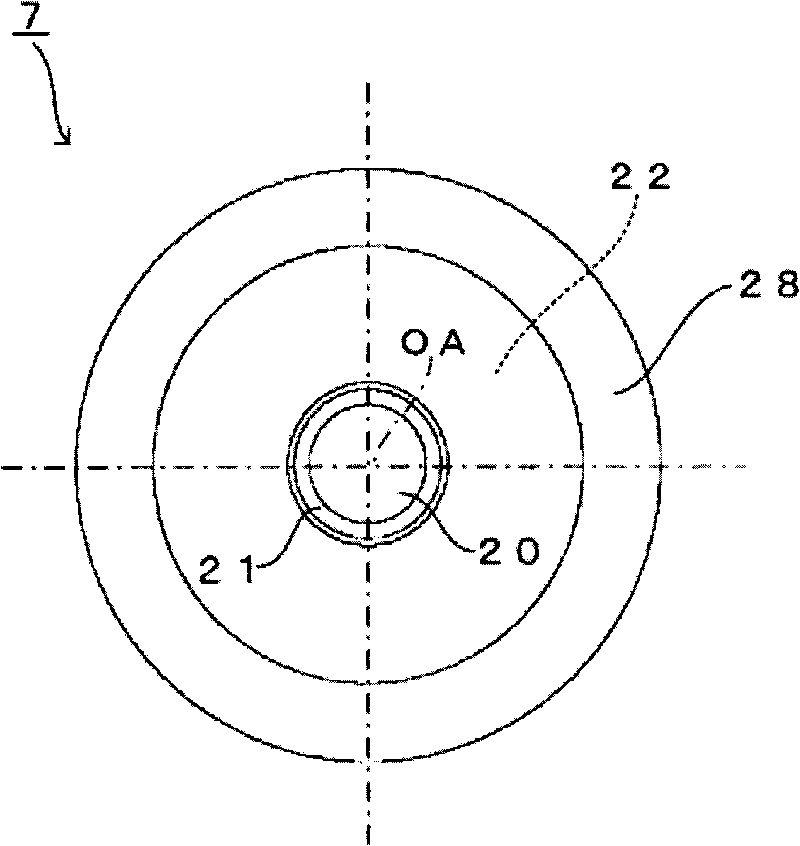
[0135] When making the lens 7 for spotlighting of this embodiment, at first in order to make the light emitted from the white light emitting diode 8 incident on the lens 7 for spotlighting, a concave portion composed of the first incident surface 20 and the second incident surface 21 is designed. , as the structure of the LED facing face.
[0136] When designing the concave portion, the size of the first incident surface 20 is mainly determined based on the FWHM of the light emitted from the spotlighting device and the illuminance distribution of the irradiated light on the illuminated surface ...
PUM
 Abstract
Description
Claims
Application Information
 - R&D
- Intellectual Property
- Life Sciences
- Materials
- Tech Scout
- Unparalleled Data Quality
- Higher Quality Content
- 60% Fewer Hallucinations
Browse by: Latest US Patents, China's latest patents, Technical Efficacy Thesaurus, Application Domain, Technology Topic, Popular Technical Reports.
© 2025 PatSnap. All rights reserved.Legal|Privacy policy|Modern Slavery Act Transparency Statement|Sitemap|About US| Contact US: help@patsnap.com