Inner flame energy-concentrating riser pipe type gas burner

A technology of gas burners and burners, which is applied in the direction of gas fuel burners, burners, and the combination of multiple burners. The effect of thermal efficiency improvement

Active Publication Date: 2010-06-09
三峰实业有限公司
View PDF0 Cites 11 Cited by
  • Summary
  • Abstract
  • Description
  • Claims
  • Application Information

AI Technical Summary

Problems solved by technology

However, because the cooking habits abroad are different from those in China, the heat load index can only meet the standard of GB16410-1996 version, and the material used is aluminum, and the melting point temperature can

Method used


Image

  • Inner flame energy-concentrating riser pipe type gas burner
  • Inner flame energy-concentrating riser pipe type gas burner
  • Inner flame energy-concentrating riser pipe type gas burner

Examples


Embodiment 1

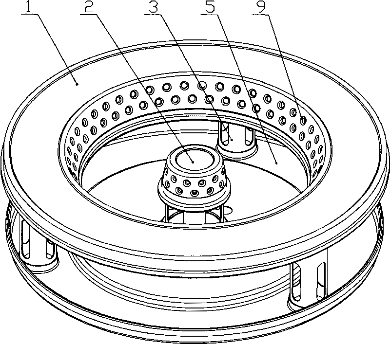
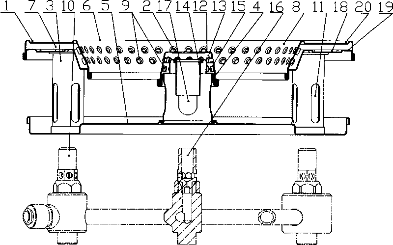
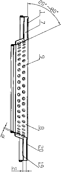
[0015] Embodiment 1: as figure 1 and figure 2 As shown, the internal flame type energy-gathering standpipe gas burner includes a large fire burner 1, a small fire burner 2, a large fire burner mixing tube 3, a small fire burner positioning tube 4 and a water storage tray 5, as image 3 As shown, the high-fire burner 1 includes an annular shell 6 and an inner cavity 7 of the annular shell. The inner ring 8 of the annular shell 6 is in the shape of a rounded frustum at an angle of 30° to the horizontal plane, and the inner ring 8 is provided with 2 fire holes. 9. There are 3 mixing tubes 3 of the high-fire burner, which are respectively vertically connected to the lower plane 18 of the annular shell 6 of the high-fire burner and the water accumulation tray 5 and are evenly distributed along the circumferential direction of the water accumulation tray 5. One end of the high-fire burner mixing tube 3 It communicates with the inner cavity 7 of the annular shell, and the other end...

Embodiment 2

[0016] Embodiment 2: The annular housing 6 of the high fire burner 1 is composed of a flat annular air intake housing 19 and a flat annular high fire combustion shell 20 connected to each other. The inner ring 8 of the flat annular high fire combustion shell 20 is in the shape of The horizontal plane is in the shape of a rounded frustum at an angle of 35°. The flat annular high-fire combustion shell 20 is arranged on the inner side of the flat annular air intake shell 19. The casing 12 is formed by punching and riveting stainless steel sheets, the mixing tube 14 of the small fire burner is connected with the round platform hat-shaped casing 12 by spot welding, and the rest are the same as in the first embodiment.

Embodiment 3

[0017] Embodiment 3: The inner ring 8 of the annular shell 6 is in the shape of a rounded truncated cone at an angle of 70° to the horizontal plane. There are 3 fire holes 9 on the inner ring 8. There are 5 mixing tubes 3 of the high-fire burner. There are 6 air intake slots 11 evenly distributed on the side of the mixing tube 3, and 3 fire discharge holes 9 are arranged on the outer surface 15 of the round platform hat-shaped housing 12, and the angle between the outer surface 15 and the horizontal plane is 80°. Four air inlets 17 are evenly distributed on the side of the positioning tube 4 of the low-fire burner, and the distance h from the upper end surface of the mixing tube 3 of the high-fire burner to the top surface of the annular housing cavity 7 is 1 And the distance h from the upper end surface of the mixing tube 14 of the small fire burner to the upper surface of the inner cavity 13 of the round platform hat-shaped shell 2 It is 4mm, and the diameter of fire hole 9 ...


PUM

PropertyMeasurementUnit
Diameteraaaaaaaaaa
Diameteraaaaaaaaaa

Abstract

The invention discloses an inner flame energy-concentrating riser pipe type gas burner, which comprises a big fire burner, a small fire burner, a mixing tube of the big fire burner, a positioning tube of the small fire burner, and a water collector. An inner ring of an annular shell of the big fire burner is an inverted frustum which forms an angle between 20 and 80 DEG with a horizontal plane, and 1 to 5 fire exhaust holes are formed on the inner ring. One end of the mixing tube of the big fire burner is connected with the annular shell and communicated with an inner cavity of the annular shell, while the other end is communicated with a big fire nozzle which is arranged on the lower part of the water collector. The small fire burner comprises a frustum cap shell and an inner cavity of the frustum cap shell, wherein 1 to 5 fire exhaust holes are formed on external side face of the frustum cap shell, and the inner cavity of the frustum cap shell is communicated with a small fire nozzle which is positioned on the lower part of the water collector by a mixing tube of the small fire burner. The inner flame energy-concentrating riser pipe type gas burner has the advantages of reasonable structure, high thermal efficiency, material conservation, convenient processing, excellent energy-saving effect, less exhaust emission and the like.

Description

technical field [0001] The invention relates to a gas burner, in particular to an internal flame gas burner. Background technique [0002] With the increasing requirements of modern families for kitchen equipment, the built-in household gas cooker used to inlay on the cooktop has achieved a certain degree of improvement in shape and appearance, but the heart of the gas cooker, that is, the burner, has not. For a big improvement, most factories only refit the traditional horizontal tube atmospheric burner on the bottom shell of the embedded gas stove. Because the primary air intake of this type of burner needs to enter from the vent on the bottom shell when it is working, the burner part cannot be isolated from the bottom shell. cause a lot of trouble. At the same time, when the traditional burner is used as a heating element, the temperature of the cooking surface will be high, especially when the nozzle is tempered due to the boiling overflow blocking the fire hole, the t...

Claims


Application Information

Patent Timeline
IPC IPC(8): F23D23/00F23D14/02
Inventor 陈观峰孔卫国孔文正陶建王永伟徐泽斌
Owner 三峰实业有限公司
Why Eureka
Try Eureka