Blast hole inner multi-point energy-gathered micro perforation type blasting method and installation structure thereof

A technology of installation structure and blast hole, which is applied in blasting, blasting barrels, weapon accessories, etc., can solve the problems of inconspicuous single consumption effect of explosives, small direct contact area, and increased blasting cost, etc., and achieves simple and easy implementation method, Easy to accept, simple structure effect

Pending Publication Date: 2020-07-03
卢文厅
View PDF1 Cites 0 Cited by
  • Summary
  • Abstract
  • Description
  • Claims
  • Application Information

AI Technical Summary

Problems solved by technology

Trace it to its cause, mainly contain the following points: First, this method mainly has some effects in reducing the blasting dust, and the effect in reducing the unit consumption of explosives is not obvious
The 2nd, the water medium that adds in this method is segmentally isolated from the explosive, and the area of ​​direct contact is very small. After the explosive explodes, the energy-absorbing chemical bond of the water medium breaks and decomposes into H 2 and O 2 lack of basis
Third, if the water bag is placed at the bottom of the blasthole, it will inevitably increase the rate of large blocks at the bottom. If the water bag is placed on the upper part of the blasthole, it is equivalent to increasing the length of the blockage, which will inevitably increase the rate of large blocks at the upper part. If the water bag is placed in the middle of the blasthole, It is inevitable to form a segmented charge, which requires an increase in the number of detonators or the use of detonating cords, increasing the cost of blasting

Method used


Image

  • Blast hole inner multi-point energy-gathered micro perforation type blasting method and installation structure thereof
  • Blast hole inner multi-point energy-gathered micro perforation type blasting method and installation structure thereof
  • Blast hole inner multi-point energy-gathered micro perforation type blasting method and installation structure thereof

Examples


Embodiment 1

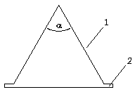
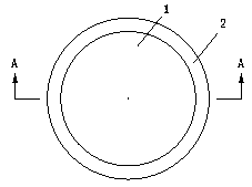
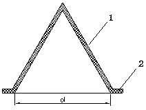
[0071] In a quarry, the stone is quarried by the medium and deep hole step blasting method. The rock is medium-hard sandstone. The diameter of the blasthole 3 is 115mm, the depth of the blasthole is 8m, and the filling is 3m. Charge 6 adopts No. 2 rock emulsion explosive with a specification of Φ70mm-2000g. Three rows of blastholes are arranged in one blasting, and the holes are arranged in a plum blossom pattern. The layout plan of the blastholes is as follows Figure 4 shown. The cone apex angle α of the energy gathering cover is taken as 60°, and the diameter of the bottom circle refers to the formula Select, actually take d = 40mm, and take 5mm for the blank holder width. The plan view of the energy-gathering hole of the energy-gathering cover is as follows: Figure 5 shown. A shaped charge pack of explosives is placed in a shaped cover, and the shaped cover is finally arranged in a folded manner in the blast hole. The structure diagram of the shaped charge in the bla...

Embodiment 2

[0073] A shaped charge pack of explosives is placed in a shaped cover, and the shaped cover is finally arranged in a reciprocating manner in the blast hole. The structure diagram of the shaped charge in the blast hole is shown in Figure 8 shown. All the other conditions are the same as in Example 1.

Embodiment 3

[0075]In the vertical middle and deep hole blasting, because the bottom rock is in a state of bidirectional or multidirectional stress, and the chassis resistance line is relatively large, the root ridges are often left at the bottom of the blasthole after blasting, and the root ridges need secondary drilling and blasting treatment or mechanical treatment. The cost of blasting is increased, which affects the construction progress. In conventional blasting, the position of the charge center is often lowered by increasing the super-depth, so as to overcome the resistance at the bottom of the step and reduce the root remaining. This approach increases the amount of drilling and charge, thereby greatly increasing the cost of blasting, and cannot completely eliminate the root ridge phenomenon. Combined application of the present invention, the enhanced micro-perforation blasting method can be used at the bottom of the blasthole, and the common micro-perforation blasting method can ...


PUM


Abstract

The invention discloses a blast hole inner multi-point energy-gathered micro perforation type blasting method and an installation structure thereof. The method includes the steps that firstly, explosive column plasticity is utilized, 1-6 energy-gathered covers with pointed-cone-shaped tops and bottom pressing edges are inserted into an explosive column from the side face of the explosive column through the pointed-cone-shaped structures on the tops till the bottom pressing edges of the energy-gathered covers face outwards and are attached to the surface of the explosive column, then the energy-gathered covers are fixed to the explosive column, manufacturing of an energy-gathered blasting cartridge is completed, and it is ensured that all the energy-gathered covers are arranged on the sameside of the explosive column; secondly, multiple energy-gathered blasting cartridges manufactured according to the first step are input into a blast hole, during inputting, it is ensured that the energy-gathered hole directions of the energy-gathered covers on the energy-gathered blasting cartridges face the free face in the radial direction, and the energy-gathered blasting cartridges are in clearance fit with the blast hole; and thirdly, blasting is conducted according to the blasting networking step of conventional deep hole blasting. By means of the blast hole inner multi-point energy-gathered micro perforation type blasting method and the installation structure thereof, the drilling number and the explosive unit consumption are reduced, the blasting efficiency is improved, and the drilling and blasting cost is obviously saved.

Description

technical field [0001] The invention belongs to the field of blasting construction, and in particular relates to a method for multi-point energy-gathering micro-perforation blasting in a blast hole and an installation structure thereof, and is especially suitable for blasting construction in medium and deep holes. Background technique [0002] The energy released when the explosive explodes in the rock mass is transmitted to the rock through the blasting stress wave and the expansion pressure of the detonation gas, causing the rock to break. But the energy actually used to break the rock is only a tiny fraction of the energy released by the explosives. Most of the energy is consumed in useless work, such as heat conduction, heat radiation, and excessive crushing and plastic deformation of the medium during the explosion, and part of the useless mechanical work is consumed in the vibration, throwing of rocks and the formation of air shock waves in the air. . When throwing b...

Claims


Application Information

Patent Timeline
Patent Type & Authority Applications(China)
IPC IPC(8): F42D3/04F42D1/00F42B3/22F42B3/087
CPCF42B3/087F42B3/22F42D1/00F42D3/04
Inventor 卢文厅
Owner 卢文厅
Why Eureka
Try Eureka