Method, device and system for measuring signal phase difference

A signal phase and difference measurement technology, applied in the field of signal measurement, can solve the problems of increasing hardware density, high hardware cost, and complicated measurement process, and achieve the effect of reducing the number, reducing hardware density, and simplifying the measurement process.

Active Publication Date: 2010-06-09
HENGQIN INT INTPROP EXCHANGE CENT CO LTD
View PDF0 Cites 12 Cited by
  • Summary
  • Abstract
  • Description
  • Claims
  • Application Information

AI Technical Summary

Problems solved by technology

[0004] The inventor found in the process of realizing the present invention that there are at least the following technical problems in the prior art: in the above-mentioned measurement process, it is necessary to set a special sampling channel for each signal, that is, as many sampling channels are needed as there are signals, This will undoubtedly increase the hardware density, which will easily cause channel coupling and cause system performance degradation. At the same time, the hardware cost will be higher, and different sampling channels have different amplification and filtering circuits. Due to device differences, each signal sampling channel also has different The transmission characteristics, especially the phase characteristics, have large differences. In the acquisition process, the transmission characteristics of each channel are usually collected first, and the measurement results need to be calibrated
To sum up, in the prior art, due to the method of using multiple sampling channels for multiple signals, the hardware density is increased and the measurement process is complicated

Method used


Image

  • Method, device and system for measuring signal phase difference
  • Method, device and system for measuring signal phase difference
  • Method, device and system for measuring signal phase difference

Examples


Embodiment Construction

[0027] The technical solutions of the present invention will be described in further detail below with reference to the accompanying drawings and embodiments.

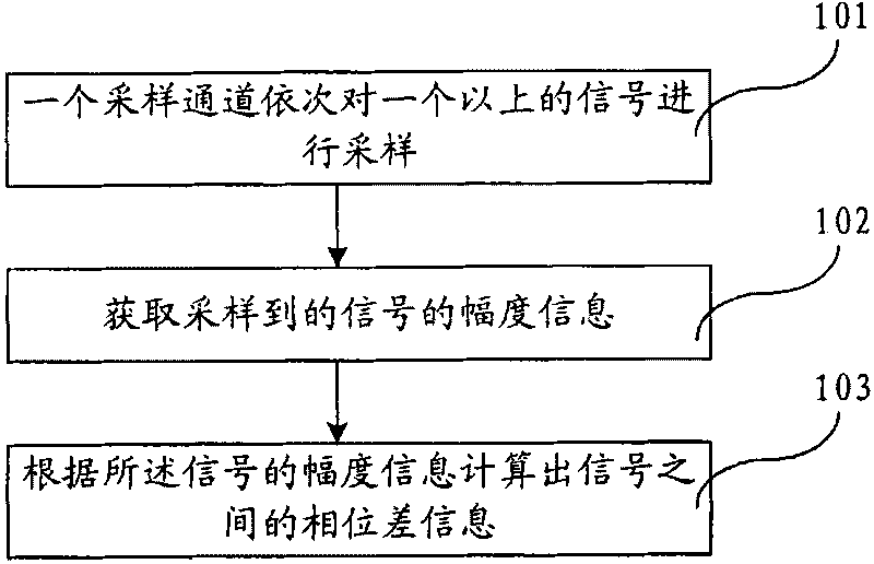
[0028] The method for measuring signal phase difference provided by the embodiment of the present invention is suitable for application in a system that needs to measure the amplitude and phase difference of multiple signals of the same network. figure 1 It is a schematic flow chart of an embodiment of the signal phase difference measurement method of the present invention, such as figure 1 As shown, the measurement process includes the following steps:

[0029] Step 101, one sampling channel sequentially samples more than two signals;

[0030] Step 102, obtaining the amplitude information of the sampled signal;

[0031] Step 103. Calculate phase difference information between signals according to the amplitude information of the signals.

[0032] In this embodiment, when measuring the phases of multiple signals in ...


PUM


Abstract

The embodiment of the invention provides a method, a device, and a system for measuring signal phase difference. The method comprises the following steps: sampling more than two signals and acquiring the amplitude information of the sampled signals by a sampling channel; and calculating phase difference information between the signals according to the amplitude information of the signals. The device comprises a sampling module, an amplitude information acquisition module, and a calculating module, wherein the sampling module comprises at least one sampling channel for sampling more than two signals; the amplitude information acquisition module is used for acquiring the amplitude information of the sampled signals; and the calculating module is used for calculating the phase difference information between the signals according to the amplitude information of the signals. The embodiment of the invention also provides the system for measuring the signal phase difference, which comprises a transmission network and the device for measuring the signal phase difference. The method, the device and the system for measuring the signal phase difference provided by the embodiment of the invention utilize one sampling channel to sample a plurality of signals, which can reduce the hardware density of the device and simplify a measurement flow.

Description

technical field [0001] Embodiments of the present invention relate to the technical field of signal measurement, and in particular, to a signal phase difference measurement method, device and system. Background technique [0002] In technical fields such as testing, communication, and control, it is often necessary to measure the phase information between multiple signals in the same network. [0003] In the existing measurement process, in order to obtain the phase difference between several signals, multiple sampling channels are usually used to sample each signal at the same time, including the following steps: first, perform a calibration test on each sampling channel, that is, calculate And store the transmission characteristics of each signal sampling channel to eliminate the influence of different channel transmission characteristics in the final measurement results, mainly to obtain parameters such as amplitude frequency and phase frequency; then multiple sampling ch...

Claims


Application Information

Patent Timeline
Patent Type & Authority Applications(China)
IPC IPC(8): G01R25/00H04B17/00
CPCH03D13/00G01R25/00G01R27/28
Inventor 孙大伟田玉周冯恩波唐利任雄伟
Owner HENGQIN INT INTPROP EXCHANGE CENT CO LTD
Why Eureka
Try Eureka