Radio frequency identification tag and method for calibrating clock signals

A clock calibration and clock signal technology, applied in the field of radio frequency identification tags, can solve the problems of increasing chip cost, reducing communication speed, increasing tag chip cost, etc., to achieve the effect of controlling cost and improving reading and writing distance

Active Publication Date: 2010-06-09
SHANGHAI FUDAN MICROELECTRONICS GROUP
View PDF0 Cites 15 Cited by
  • Summary
  • Abstract
  • Description
  • Claims
  • Application Information

AI Technical Summary

Problems solved by technology

[0014] Some high-precision capacitors and resistors can be used in the process to reduce this deviation, but this method will significantly increase the cost of the chip
In circuit design, the clock can be dynamically calibrated by a method similar to a phase-lock loop (Phase-Lock Loop), but this method will add too many circuits to the label and increase the cost of the label chip
In the protocol, a clock calibration can be performed before each communication between the reader and the tag, but this method consumes too much communication time and reduces the communication speed

Method used


Image

  • Radio frequency identification tag and method for calibrating clock signals
  • Radio frequency identification tag and method for calibrating clock signals
  • Radio frequency identification tag and method for calibrating clock signals

Examples


Embodiment approach

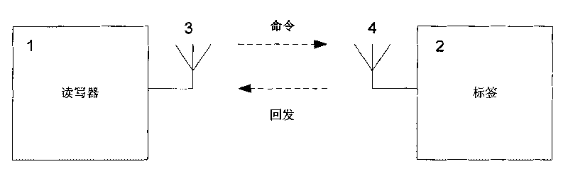
[0087] The present invention provides a radio frequency identification tag for calibrating the clock signal, the tag 2 is connected to the reader 1 through a signal;

[0088] The reader 1 contains one or more antennas 3, and the tag 2 contains one or more antennas 4. The reader 1 sends commands to the tag 2 through the antenna 3 to operate the tag 2, and the tag 2 receives the reader through the antenna 4. The commands sent out, and these commands are processed through the circuit on the tag 2, and the corresponding data is sent back to the reader 1 through the antenna 4;

[0089] Such as Figure 6 As shown, the label 2 contains:

[0090] A signal demodulation circuit 5, the signal demodulation circuit 5 is connected to the interface of the antenna 4 through the circuit;

[0091] A command processing circuit 6, the command processing circuit 6 is connected to the signal demodulation circuit 5 through a circuit;

[0092] A non-volatile memory 7, the non-volatile memory 7 is ...


PUM


Abstract

The invention provides a radio frequency identification (RFID) tag circuit and method for calibrating clock signals. An RFID tag circuit counts the specific duration signal emitted by a reader-writer, adjusts the clock calibration bit segment according to the counting results and writes the clock calibration bit segment into a nonvolatile memory of the tag. During next electrifying, the tag needs not to calibrate the clock again and only needs to read the clock calibration bit segment from the nonvolatile memory and adopts the clock calibration bit segment to control the circuit of an oscillator of the tag to obtain accurate clock signals. The invention ensures the clock signals generated by the tag circuit to meet the requirement of RFID protocol, correctly decodes the data sent by the reader-writer to the tag, correctly posts data back to the reader-writer, simultaneously controls the power consumption of the tag and enlarges the read-write distance of the tag.

Description

technical field [0001] The invention relates to a radio frequency identification tag for calibrating clock signals and a method for calibrating the clock signals in the circuit. Background technique [0002] Radio Frequency Identification (RFID) technology is widely used in logistics tracking, identity authentication and other applications. The RFID system usually includes tag readers and tags, such as figure 1 As shown, 1 is the reader and 2 is the tag. The reader includes one or more antennas 3 , and the tag includes one or more antennas 4 . The reader-writer 1 sends data such as commands to the tag 2 through the antenna 3, and the tag 2 processes the received commands and sends data back to the reader-writer through the antenna 4. [0003] When the reader 1 sends a command to the tag 2, it usually sends a start signal first, and then sends command data such as data 0, 1, etc. These start signals are used to synchronize the command or pass some link parameters, such as f...

Claims


Application Information

Patent Timeline
Patent Type & Authority Applications(China)
IPC IPC(8): G06K19/073G06K7/00H03L7/24
Inventor 罗恰嗣李清张纲王磊宁兆熙
Owner SHANGHAI FUDAN MICROELECTRONICS GROUP
Why Eureka
Try Eureka