Releasing device of electric installation equipment and electric installation equipment having the releasing device

A release device, electrical installation technology, applied in the direction of electrical components, emergency protection devices, protective switch operation/release mechanisms, etc.

Inactive Publication Date: 2010-06-09
SIEMENS AG
View PDF2 Cites 3 Cited by
  • Summary
  • Abstract
  • Description
  • Claims
  • Application Information

AI Technical Summary

Problems solved by technology

[0008] In DE 11221188A, the two electromagnetic elements attracted to each other are only described by their layout and construction, without the use of connections, intermediate links or contacts to ensure free release

Method used


Image

  • Releasing device of electric installation equipment and electric installation equipment having the releasing device
  • Releasing device of electric installation equipment and electric installation equipment having the releasing device
  • Releasing device of electric installation equipment and electric installation equipment having the releasing device

Examples


Embodiment Construction

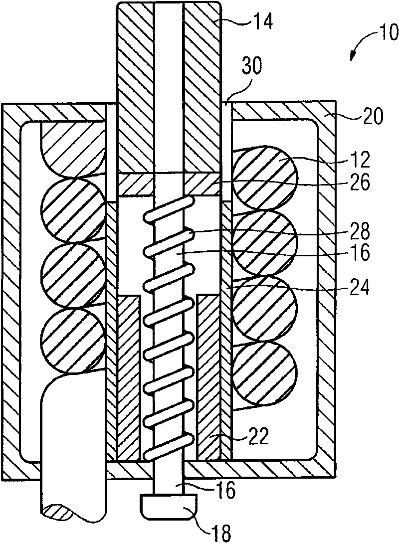
[0030] exist figure 1 The release device for a circuit breaker shown generally at 10 includes a coil 12 . The job of this coil is to generate a magnetic field. This magnetic field pulls the armature 14 into the coil to move the plunger 16 coupled to the armature and the plunger end 18 of the plunger 16 releases a mechanism not shown in this figure. The coil 12 is surrounded by a yoke 20 of soft magnetic material. The armature 14 passes through an opening in the yoke so that a magnetic circuit extending over the yoke 20 can be closed by the armature 14 .

[0031]The yoke 20 is provided with a core 22 . This core extends inside the coil 12 . This core 22 is arranged in a sleeve 24 . The function of this sleeve 24 is to guide the armature 14 during its movement. An insulating disk 26 is arranged on the armature 14 . This insulating disc protects the armature against arcing.

[0032] A spring 28 is provided as in conventional release devices. This spring presses against t...


PUM


Abstract

The invention relates to a releasing device of electric installation equipment and an electric installation equipment having the releasing device. For delaying the circuit breaker releasing, the invention provides a releasing device 10, 110, wherein a ferromagnet 30, 136 in serial connection with a releasing coil 12, 112 holds an armature 14, 114 which is going to move; when the current strength is determined, the ferromagnet 30, 136 is heated to temperature above the Curie point of the ferromagnet, thereby, the ferromagnet loses its permanent magnetisation and no longer holds the armature 14, 114; and the armature 14 can move into the coil 12, 112. Therefore, the original releasing process is delayed, and the delaying time is the time for heating the ferromagnet 30 to the temperature above the Curie point of the ferromagnet.

Description

technical field [0001] The invention relates to a release device for electrical installation equipment. Included in the concept "release" is breaking the current loop. The main field of application of the invention is circuit breakers. Release is the main task of the circuit breaker. Background technique [0002] In the release device of the invention, the release should be done purely electromechanically. In this case, it relates to the disclosed embodiments of the release device. Known embodiments include an electrical coil through which, in the basic state, the current to be monitored flows. The armature is pressed by a spring in the direction out of the electric coil, wherein the spring (in the case of the electric coil having a cylindrical configuration and the spring in a cylindrical configuration) is typically at least partially arranged within the electric coil. The armature can be moved into the electric coil against the force of the spring. This movement can ...

Claims


Application Information

Patent Timeline
Patent Type & Authority Applications(China)
IPC IPC(8): H01H71/32H01H71/14
CPCH01H71/2463H01H71/142
Inventor R·莫斯泰特
Owner SIEMENS AG
Why Eureka
Try Eureka