Method and device for testing audio loop of communication terminal
A communication terminal and audio technology, applied in the field of communication, can solve the problem of low cost, and achieve the effect of low cost, high degree of system integration, and high degree of test automation
- Summary
- Abstract
- Description
- Claims
- Application Information
AI Technical Summary
Problems solved by technology
Method used
Image
Examples
Embodiment 1
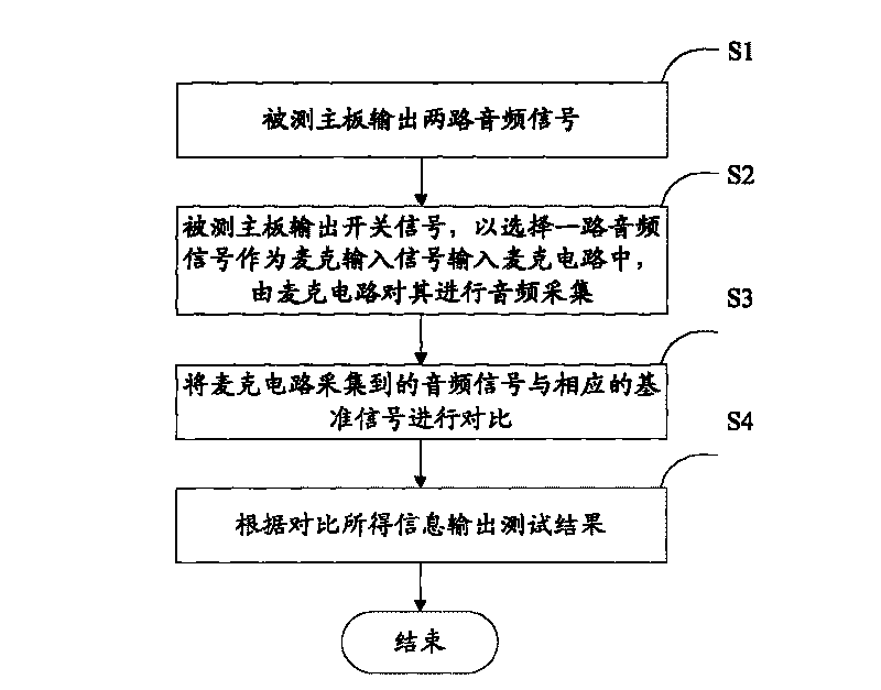
[0028] figure 1 It is a flow chart of the method in Embodiment 1 of the present invention, such as figure 1 As shown, the method includes the following main steps:
[0029] S1. The motherboard under test selects an audio file and plays it, and outputs two audio signals.
[0030] S2. The main board under test outputs a switching signal to select one audio signal as a microphone input signal and input it into the microphone circuit, and the microphone circuit performs audio collection on it.
[0031] S3. Comparing the audio signal collected by the microphone circuit with the corresponding reference signal.
[0032] S4. Output the test result according to the information obtained from the comparison.
[0033] In the above step S1, the audio file selected by the main board under test may be an audio file pre-stored by itself.
[0034] In the above step S2, the logic of selecting the audio signal is as follows: after the test result of one selected audio signal is obtained, if ...
Embodiment 2
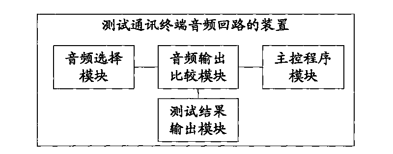
[0036] figure 2 It is a schematic diagram of the device structure in Embodiment 2 of the present invention, such as figure 2 As shown, the device described in this embodiment includes: an audio output comparison module, an audio selection module and a test result output module.
[0037] Among them, the audio output comparison module is used to control the main board under test to output two audio signals and switch signals, and compare the audio signal collected by the microphone circuit with the corresponding reference signal.
[0038] The audio selection module is used to receive two audio signals and switch signals output by the main board under test, and through the selection of the switch signals, the selected audio signal is input into the microphone circuit as a microphone input signal for audio collection.
[0039] The test result output module outputs the test result according to the information obtained by the comparison of the audio output comparison module.
[...
Embodiment 3
[0042] Based on the above embodiments 1 and 2, in specific implementation, the audio selection module can be completed by hardware; the audio output comparison module, test result output module and main control program module can be completed by software.
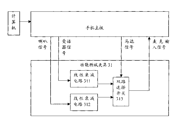
[0043] image 3 It is a schematic diagram of the specific implementation in Embodiment 3 of the present invention, such as image 3 As shown, the hardware part can specifically be a functional test fixture 31 , which includes two linear attenuation circuits 311 and 312 and a dual selection switch 313 . The signals are speaker signal, receiver signal, motor signal and microphone input signal. The speaker and the receiver of the mainboard under test respectively output fixed-frequency audio signals, which are attenuated by the linear attenuation circuits 311 and 312 and then input to the two input terminals of the dual-way selector switch 313 . The two-way selector switch 313 receives the motor signal and is controlled by the...
PUM
 Abstract
Description
Claims
Application Information
 - R&D
- Intellectual Property
- Life Sciences
- Materials
- Tech Scout
- Unparalleled Data Quality
- Higher Quality Content
- 60% Fewer Hallucinations
Browse by: Latest US Patents, China's latest patents, Technical Efficacy Thesaurus, Application Domain, Technology Topic, Popular Technical Reports.
© 2025 PatSnap. All rights reserved.Legal|Privacy policy|Modern Slavery Act Transparency Statement|Sitemap|About US| Contact US: help@patsnap.com


