Light-emitting diode drive circuit and transistor switching module thereof

A transistor switch, light-emitting diode technology, applied in circuit layout, lamp circuit layout, light source and other directions

Inactive Publication Date: 2010-06-09
GREEN SOLUTION TECH CO LTD
View PDF0 Cites 17 Cited by
  • Summary
  • Abstract
  • Description
  • Claims
  • Application Information

AI Technical Summary

Problems solved by technology

The rise of the gate-to-source capacitance (Cgs) also causes the error amp

Method used


Image

  • Light-emitting diode drive circuit and transistor switching module thereof
  • Light-emitting diode drive circuit and transistor switching module thereof
  • Light-emitting diode drive circuit and transistor switching module thereof

Examples


Embodiment Construction

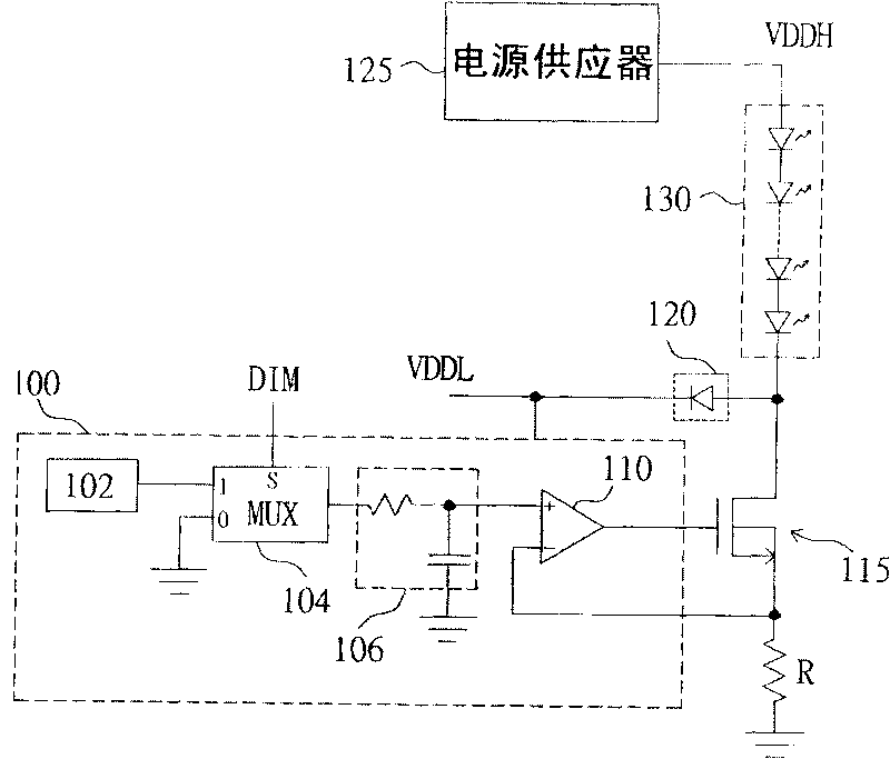
[0034] Please refer to figure 2 , is a schematic circuit diagram of a transistor switch module used in a light emitting diode driving device according to a preferred embodiment of the present invention. The LED driving device includes a dimming control unit 100 , a transistor switch 115 , a voltage clamping element 120 , a power supply 125 and a LED module 130 . The power supply 125 is coupled to one end of the LED module 130 to provide a driving voltage VDDH to drive the LED module 130 to emit light. The transistor switch 115 has a control terminal, a first terminal and a second terminal, the first terminal is coupled to the light-emitting diode module 130, the second terminal is coupled to a reference potential (for example: ground), the control terminal receives the signal from the dimming control unit 100 generates a control signal. The dimming control unit 100 includes a reference voltage generator 102 , a multiplexer 104 , a filter circuit 106 and an error amplifier 1...


PUM


Abstract

The invention uses a voltage clamping element to clamp the potential of the drain of the metal-oxide semiconductor transistor to reduce the voltage resistant demand of the metal-oxide semiconductor transistor, when the metal-oxide semiconductor transistor used for controlling the current of the light-emitting diode module is cut off. Therefore, the cost of the light-emitting diode drive device can be greatly reduced and the power consumption of the metal-oxide semiconductor transistor can also be reduced, thus increasing the efficiency of the entire circuit.

Description

technical field [0001] The present invention relates to a transistor switch module and a light-emitting diode drive circuit using the transistor switch module, in particular to a transistor switch module with voltage clamping function and a light-emitting diode drive circuit using the transistor switch module. Background technique [0002] Please refer to figure 1 , is a known light-emitting diode driving device. The LED driving device includes a dimming control unit 10 , an error amplifier 15 , an NMOS transistor 20 , a power supply 25 , an LED module 30 and a current detection resistor R. The power supply 25 is coupled to one end of the LED module 30 to provide a driving voltage to drive the LED module 30 to emit light. The NMOS transistor 20 is coupled to the other end of the LED module 30 , and controls the magnitude of the current flowing through the LED module 30 according to a switch control signal. The current detection resistor R is coupled to the NMOS transistor...

Claims


Application Information

Patent Timeline
IPC IPC(8): H05B37/02F21V23/00F21Y101/02
Inventor 徐献松余仲哲柳娟娟
Owner GREEN SOLUTION TECH CO LTD
Why Eureka
Try Eureka