Waste circuit board hook pulling and dismounting device
A technology for waste circuit boards and dismantling devices, which is applied in the direction of electronic waste recycling, solid waste removal, and tool manufacturing, and can solve the problem that the overall disassembly equipment of waste circuit boards is not well solved, and cannot provide circuit board plane force, The circuit board cannot be well sealed and other problems, so as to achieve the effect of fast heating, avoiding mutual temperature, and avoiding harm
- Summary
- Abstract
- Description
- Claims
- Application Information
AI Technical Summary
Problems solved by technology
Method used
Image
Examples
Embodiment 1
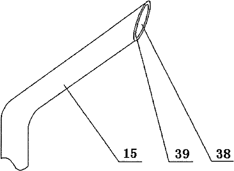
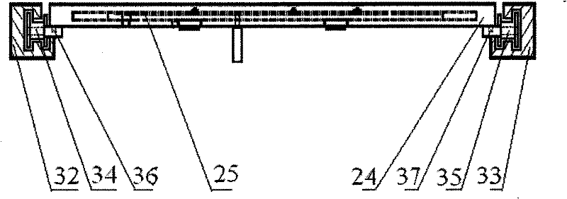
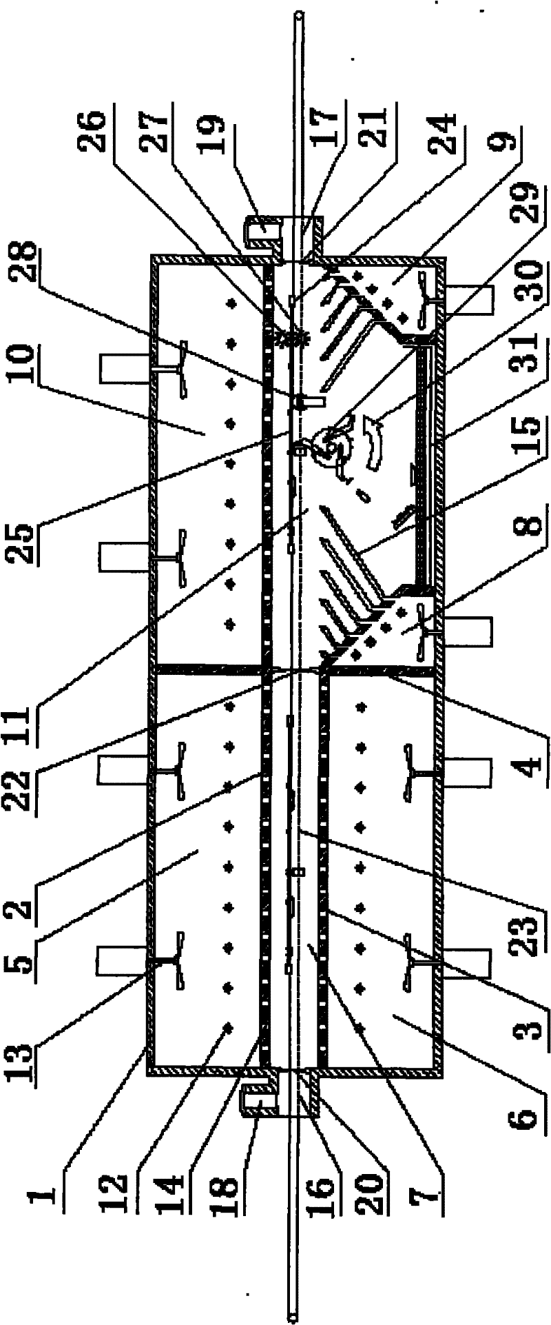
[0046] join figure 1 , The hooking and dismounting device for waste circuit boards in this embodiment includes a chassis, a heating system, a double chain transmission mechanism, a hooking mechanism, and a double roller brush mechanism. The upper partition 2, the lower partition 3 and the vertical partition 4 divide the space of the cabinet 1 into the upper preheating air box 5, the lower preheating air box 6, the preheating zone 7, the upper high temperature bellows 10 and the high temperature zone 11, and the high temperature zone There are hook pull mechanism 29, supporting wheel 28, upper steel wire roller brush 26 and lower steel wire roller brush 27, and there is a component and solder collection plate 31 under the high temperature zone 11, which separates the surrounding environment from the preheating zone 7 and is an entrance flexible partition 20. Separate the preheating zone 7 and the high temperature zone 11 as an intermediate flexible partition 22, and separate th...
Embodiment 2
[0060]In order to simplify the structure of the hook-pull mechanism in Embodiment 1 and reduce the manufacturing difficulty, this embodiment adopts the method of integrating the return coil spring and the hook.
[0061] see Figure 7 , the hook pulling mechanism of this embodiment is composed of coil spring hooks 48 and anti-swing washers 49 alternately strung on the secondary rotating shaft 42. The short end of the coil spring hook 48 is pressed on the main rotating shaft 41, and the middle part of the long end of the hook is pressed on the On the limit rod 43, the direction of the crotch is the same as the rotation direction 30 of the hook pulling mechanism, and the adjacent coil spring hooks 48 are separated by anti-swing washers 49. The hooking mechanism of this embodiment uses a coiled spring hook 48 to replace the rigid hook 44 and the return spring 46 of the first embodiment. The coiled spring hook 48 can not only hook and pull out components, but also automatically res...
Embodiment 3
[0064] see Figure 8 , the present embodiment further simplifies the hooking mechanism. The main rods of 8 elastic hooks 51 are affixed on the outer circle of the elastic hook rotating column 50 by the opposite direction of the hook pulling mechanism rotation direction 30, and the pointing of the crotch is identical with the hook pulling mechanism rotation direction 30, and a plurality of elastic hook rotating columns 50 is connected in series on the main rotating shaft 41. The bending of the elastic hook 51 itself can make it rotate at a certain angle, and can also reset automatically, so the secondary rotating shaft 42 and the reset coil spring 46 in the first embodiment are not required. Such as Figure 8 As shown, the rotation direction of the hook pulling mechanism is counterclockwise when it works, and in the rotation direction, the fixed end of the elastic hook 51 is located in front of the tip of the hook.
[0065] The advantage of this embodiment is that the mechan...
PUM
 Abstract
Description
Claims
Application Information
 - R&D
- Intellectual Property
- Life Sciences
- Materials
- Tech Scout
- Unparalleled Data Quality
- Higher Quality Content
- 60% Fewer Hallucinations
Browse by: Latest US Patents, China's latest patents, Technical Efficacy Thesaurus, Application Domain, Technology Topic, Popular Technical Reports.
© 2025 PatSnap. All rights reserved.Legal|Privacy policy|Modern Slavery Act Transparency Statement|Sitemap|About US| Contact US: help@patsnap.com


