Blowing mechanisms of knitting circular weft knitting machine

A technology of circular knitting machine and electric fan, which is applied in the directions of knitting, textile and paper making, etc., to achieve the effect of good blowing effect, concentrated blowing airflow and high strength

Inactive Publication Date: 2010-06-16
吴江天龙针织有限公司
View PDF0 Cites 3 Cited by
  • Summary
  • Abstract
  • Description
  • Claims
  • Application Information

AI Technical Summary

Problems solved by technology

However, the place where flying catkins are easy to accumulate is not only on the yarn feeder
The current blowing mechanism is helpless for the flying catkins accumulated in the hole of the yarn guide disc

Method used


Image

  • Blowing mechanisms of knitting circular weft knitting machine
  • Blowing mechanisms of knitting circular weft knitting machine
  • Blowing mechanisms of knitting circular weft knitting machine

Examples


Embodiment Construction

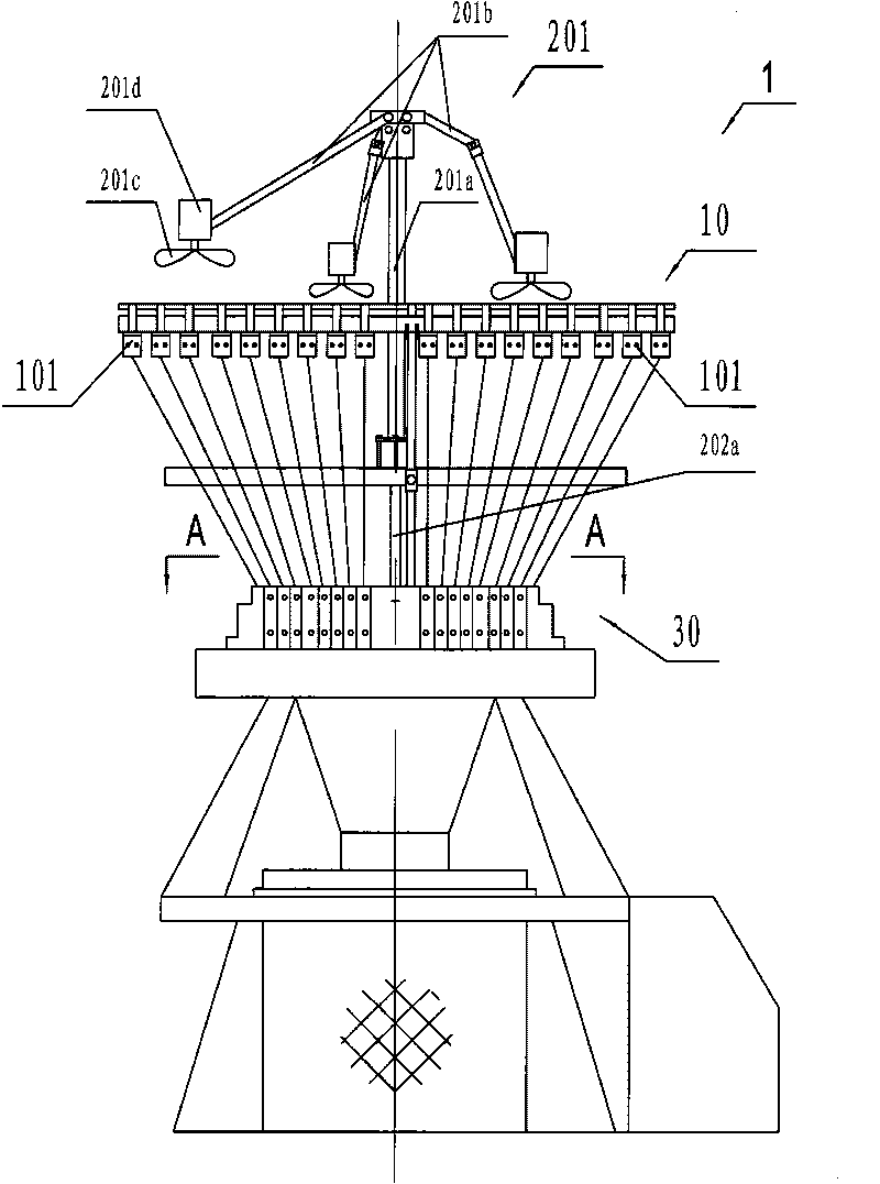
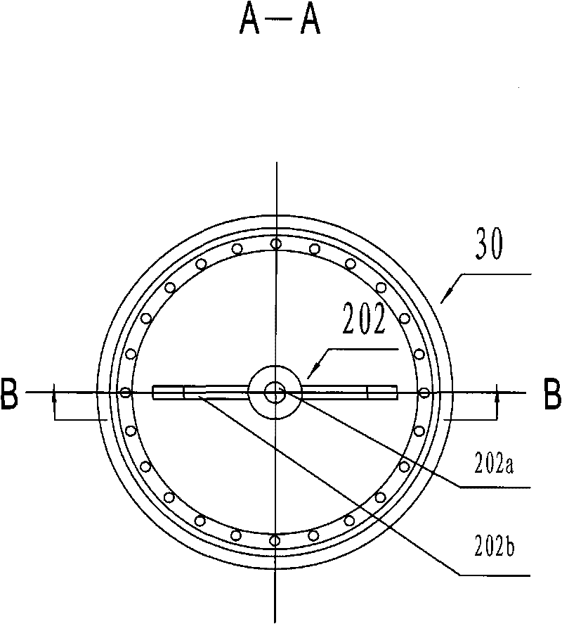
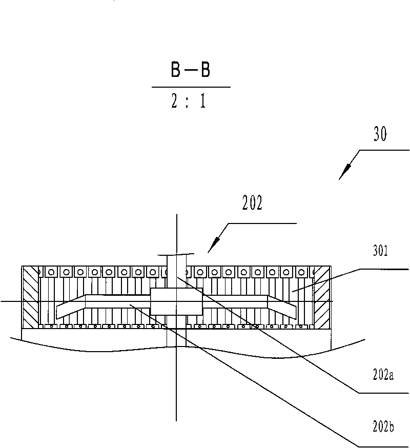
[0015] figure 1 It is a structural schematic diagram of the circular knitting machine of the present invention. As shown in the figure, the circular knitting machine 1 includes a yarn feeding device 10, a blowing mechanism and a yarn guide disc 30. The blowing mechanism includes two sets of blowing mechanisms, namely an upper set of blowing mechanisms 201 and a lower set of blowing mechanisms 202. The yarn feeding device 10 is used as the yarn feeding device of the circular knitting machine 1, and it is mainly composed of a plurality of yarn feeding devices 101 located on the top of the circular knitting machine 1 and distributed around the circumference.

[0016] The upper set of blowing mechanism 201 includes a rotating rod 201a, a bracket 201b, an electric fan 201c, an electric fan driving source 201d, and a rotating rod driving source (not shown in the figure). The center portion of the yarn feeding device 10 is provided with a rotating rod 201a, one end of the support 20...


PUM


Abstract

The invention relates to blowing mechanisms of a knitting circular weft knitting machine, which comprise two groups of the blowing mechanisms, wherein the upper group of the blowing mechanisms use an electric fan which rotates around a rotating rod and generates a blowing effect; the lower group of the blowing mechanisms use a gas blow pipe which rotates around a rotating shaft and generates the blowing effect; and the rotation direction of the rotating rod is opposite to that of the rotating shaft. The blowing mechanisms can simultaneously process flying cotton wools of a plurality of parts, and the lower group of the blowing mechanisms adopts the gas blow pipe, so the blowing mechanisms have concentrated blowing air flows and large force, and has an especially obvious effect of blowing away the flying cotton wools at holes. The blowing mechanisms process the flying cotton wools of a plurality of parts in time to improve the spinning quality of the circular weft knitting machine, and reduce the uppermost pollutant sources of the circular weft knitting machine and the main surrounding environment.

Description

technical field [0001] The invention relates to textile machinery, in particular to a blowing mechanism of a circular knitting machine. Background technique [0002] As one of the most commonly used textile machines in the textile industry, the circular knitting machine is used to weave knitted fabrics made of pure cotton yarn and various blended yarns. During the weaving process of the circular weft machine, a large amount of yarn wool will be produced, which will form flying flocs in the air. If it is not cleaned up in time, it will accumulate in many parts such as the yarn feeder and the hole of the yarn guide disc, which will not only affect the circular weft The normal operation of the machine and the textile quality, and it will also become the main source of pollution of the circular weft machine and the surrounding environment. [0003] In order to solve the troubles caused by flying catkins, the existing blowing mechanism is: a blowing mechanism is set on the upper...

Claims


Application Information

Patent Timeline
Patent Type & Authority Applications(China)
IPC IPC(8): D04B35/32D04B35/00
Inventor 朱娟
Owner 吴江天龙针织有限公司
Why Eureka
Try Eureka