
Synthetic focusing method capable of inducing polarization well logging

A technology of excited polarization and focusing method, applied in the field of synthetic focusing, which can solve the problems such as the lack of patents and literatures of excited polarization logging synthetic focusing method, the shallow detection depth and insufficient resolution of non-focusing excited polarization logging tools

Inactive Publication Date: 2010-06-16
BC P INC CHINA NAT PETROLEUM CORP +1
View PDF0 Cites 3 Cited by
  • Summary
  • Abstract
  • Description
  • Claims
  • Application Information

AI Technical Summary

Problems solved by technology

[0004] However, due to the shallow detection depth of the non-focus induced polarization logging tool, the detection depth is 0.6-0.8 meters, the resolution is not enough, the layering ability is 1 meter, and it is greatly affected by the borehole, surrounding rock and intrusion zone , thus affecting its measurement accuracy and application range
[0005] According to the online search by Hubei Provincial Information Retrieval Center, no patents and documents related to the synthetic focusing method of induced polarization logging have been found so far.

Method used


Image

  • Synthetic focusing method capable of inducing polarization well logging
  • Synthetic focusing method capable of inducing polarization well logging
  • Synthetic focusing method capable of inducing polarization well logging

Examples


Embodiment Construction

[0015] The present invention will be further described in detail below in conjunction with the accompanying drawings and specific embodiments.

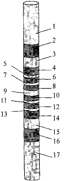
[0016] The electrode system of the present invention has nine annular electrodes embedded in a cylindrical insulating rod. 9 is the main electrode A0, 7, 11 and 5, 13 are two pairs of monitoring electrodes M1, M1' and M2, M2', 3, 15 and 1, 17 are two pairs of shielding electrodes A1, A1' and A2, A2', With the main electrode as the center, each pair of electrodes is symmetrically arranged relative to the A0 electrode, and each pair of electrodes is short-circuited with each other. 2,4,6,8,10,12,14,16 are insulating rods. The power supply loop electrode B and the measurement loop electrode N are placed relatively infinitely far away.

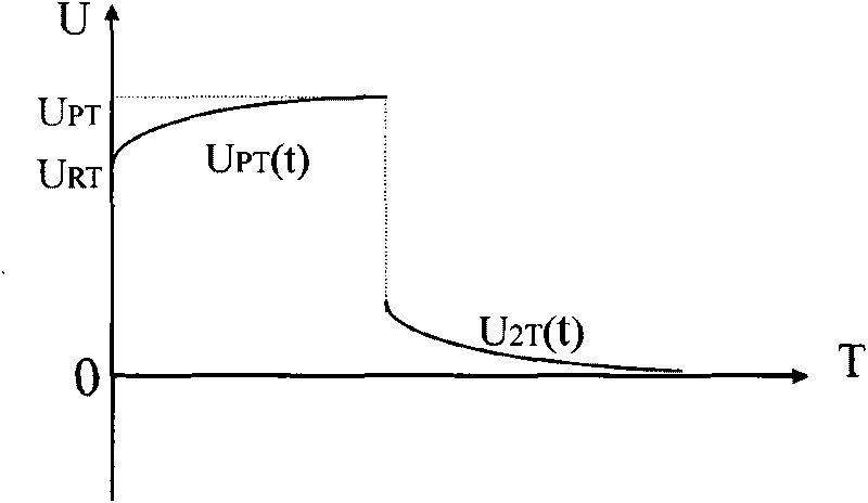
[0017] UPT is the split field polarization potential, which means UPT0(M1), UPT0(M2), UPT1(M1), UPT1(M2), URT is the split field primary potential, U2T(t) is the split field secondary Potential decay c...


PUM


Abstract

The invention relates to a synthetic focusing method capable of inducing polarization well logging. According to the synthetic focusing method, nine annular electrodes are embedded in a columniform insulating rod to form an electrode system, wherein two pairs of monitor electrodes and two pairs of shielding electrodes are symmetrically arranged with a main electrode in the center; the electrodes are short-circuit mutually; a well logging is divided into a plurality of split fields to supply power separately, and corresponding split field inducing polarization potential of the split fields and a secondary potential attenuation curve after power-off are recorded; split field secondary potential is equivalent to the split field inducing polarization potential to obtain an inducing polarization potential curve during power supplying of the split field; and then polarization total field potential is synthesized by means of an electric field superposition principle and equipotential focusing synthetic conditions to obtain the attenuation curve of primary potential, inducing polarization total field potential and the secondary potential, a specific resistance and polarizability well logging curve after focusing. The synthetic focusing method has the advantages that the detection depth of the method reaches 2.4m, while the layering capability reaches 0.5m; and meanwhile, the method can reduce influences on inducing polarization well logging caused by boreholes, wall rocks and invaded zones, thereby increasing both the layering capability and measuring precision.

Description

Technical field: [0001] The invention relates to a well logging method for petroleum geological exploration and metal mineral deposit exploration. In particular, a synthetic focusing method for induced polarization logging that can be used for deep and shallow surveys. Background technique: [0002] Among the existing foreign technologies, Amoco and Shell in the United States have developed experimental non-focused frequency-domain and time-domain combined induced polarization logging tools, and Russia also attaches great importance to the induced polarization logging methods and instruments. In the research, a non-focused excitation polarization instrument has been developed that can simultaneously measure 15 parameters from three electrodes. [0003] my country has also developed a non-focus induced polarization logging tool, which has been popularized and applied in oil fields, and has achieved certain geological effects. [0004] However, due to the shallow detection d...

Claims


Application Information

Patent Timeline
IPC IPC(8): E21B49/00G01V3/22
Inventor 李剑浩章海宁
Owner BC P INC CHINA NAT PETROLEUM CORP
Learn More