Full-automatic and unpowered sealed type oil-water separator

An oil-water separator and oil-water separation tank technology, applied in chemical instruments and methods, water/sewage multi-stage treatment, water/sludge/sewage treatment, etc., can solve the problem of increased treatment costs, high power consumption, secondary pollution, etc. problems, to achieve the effect of reducing equipment footprint, reducing equipment investment, and preventing pollution

Inactive Publication Date: 2014-03-19
邱熙
View PDF4 Cites 4 Cited by
  • Summary
  • Abstract
  • Description
  • Claims
  • Application Information

AI Technical Summary

Problems solved by technology

The disadvantages of this method are: (1), the equipment occupies a large area; (2), the oil-water separation and oil slick collection effect is poor, (3), the oil slick is in contact with the air in a large area, and it is easy to pollute the surrounding environment
The disadvantages of this method are: (1), the equipment investment is expensive; (2), the power consumption is large, and the use cost is high; (3), when the oil-water mixture contains many other phase impurities, it needs to pass through multiple sieves , Separation of process flow
The disadvantages of this method are: (1), gas source generation requires additional gas source equipment and power consumption; (2), when there are many suspended particles in the oil-water mixture, the dissolved gas releaser is easy to block
The defect of this method is: (1), the use of chemical agents will increase the processing cost; (2), adding chemical agents may cause secondary pollution
The disadvantages of this method are: (1), equipment investment is expensive; (2), filtration, circulation and backwashing consume a lot of power, and the cost of use is high; (3), chemical agents need to be added during backwashing, and it is possible to handle it improperly cause secondary pollution

Method used


Image

  • Full-automatic and unpowered sealed type oil-water separator

Examples


Embodiment Construction

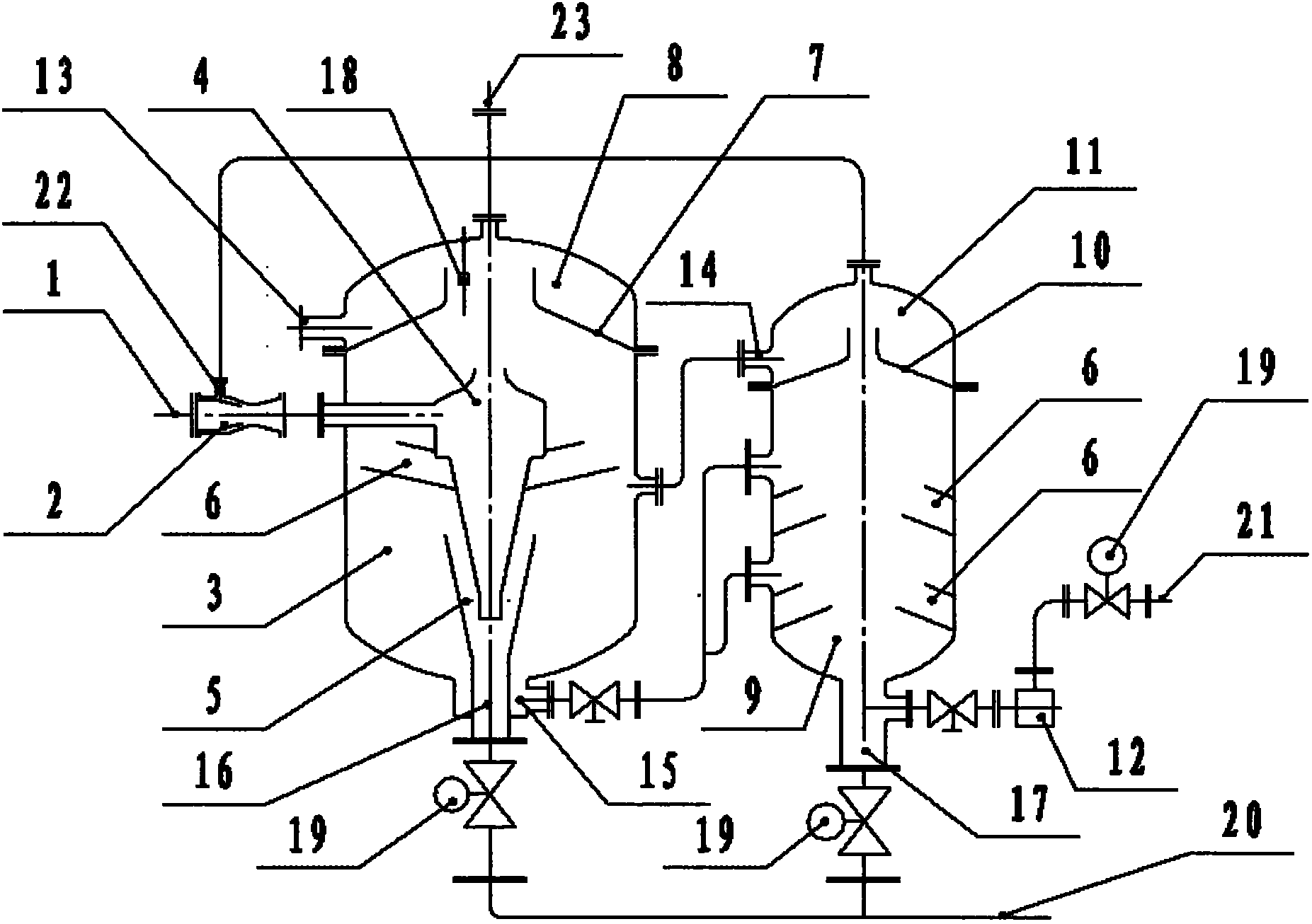
[0031] A fully automatic non-powered sealed oil-water separator of the present invention consists of an oil-water inlet pipe 1, a jet device 2, a first-stage oil-water separation tank 3, a cyclone 4, a mud-sand separation cover 5, an oil-separating cover 6, an oil-collecting Cover (1) 7, oil gathering chamber (1) 8, second stage oil-water separation tank 9, oil gathering cover (2) 10, oil gathering chamber (2) 11, oil filter 12, oil discharge outlet (1) 13 , oil discharge outlet (2) 14, drain outlet (1) 15, mud and sand outlet (1) 16, mud and sand outlet (2) 17, liquid level controller 18, electric ball valve 19, sewage outlet 20, drain (2 ) 21, ejector air inlet 22, external air inlet and outlet 23 and related pipelines and control system, characterized in that: the oily water inlet pipe 1 passes through the ejector 2 and related pipelines and the first stage oil-water separation tank The cyclone 4 in 3 is connected; the upper part of the cyclone is provided with an oil colle...


PUM


Abstract

The invention relates to a full-automatic and unpowered sealed type oil-water separator. According to the market use conditions of an existing product and based on the use characteristics of water, oil and gas, the mixing and air flotation diffusion separation technology of water, oil and gas of an ejector, centrifugal separation technology of oil and water of a whirlcone and sedimentation method gravity separation technology are comprehensively adopted to realize the full-automatic and unpowered sealed type oil-water separator through the joint use of the electric programming, detection and switch technology and the joint use of dynamic separation technology and static separation technology. Theoretically, the full-automatic and unpowered sealed type oil-water separator is an overall thinking innovation for an existing sedimentation method gravity separation theory which is a static separation theory requiring of reducing the flowing speed and impact of an inlet liquid of the oil-water separation tank to accelerate the oil-water separation effect. The full-automatic and unpowered sealed type oil-water separator aims to provide an oil-water separator with high oil-water separation rate, small floor area, low investment cost, zero mechanical use failure, convenient use and maintenance, and no smelling pollution to a processing site; and the oil-water separator is particularly suitable for oil-water separation of restaurant kitchen industry.

Description

technical field [0001] The invention relates to an oil-water separator, in particular to a fully automatic non-powered sealed oil-water separator. Background technique [0002] At present, the oil-water separation methods mainly include gravity separation, centrifugal separation, air flotation separation, chemical separation and ultrafiltration separation. in: [0003] 1. Gravity separation. This method takes advantage of the difference in density between oil and water. When the relatively light components in the oil-water liquid phase are in a laminar flow state, the heavier components settle according to the motion law of the Stokes formula. Enlarging the settling area and increasing the settling velocity of water are the main ways to improve the oil-water treatment capacity of this method. Because of the simple method, no power machinery, and low cost of use and maintenance, it is the most widely used so far. The disadvantages of this method are: (1), the equipment oc...

Claims


Application Information

Patent Timeline
Patent Type & Authority Applications(China)
IPC IPC(8): C02F9/02
Inventor 邱熙
Owner 邱熙
Why Eureka
Try Eureka