Steam compressor arrangement

A vapor compression and compressor technology, which is applied in steam engine devices, components of pumping devices for elastic fluids, and steam applications, etc., can solve problems such as ineffective utilization and increase in compressor temperature, and achieve effective energy and efficient utilization. Effect

Inactive Publication Date: 2010-06-16
KOBE STEEL LTD
View PDF1 Cites 11 Cited by
  • Summary
  • Abstract
  • Description
  • Claims
  • Application Information

AI Technical Summary

Problems solved by technology

Not only can this heat not be used effectively, but it

Method used


Image

  • Steam compressor arrangement
  • Steam compressor arrangement
  • Steam compressor arrangement

Examples


Embodiment Construction

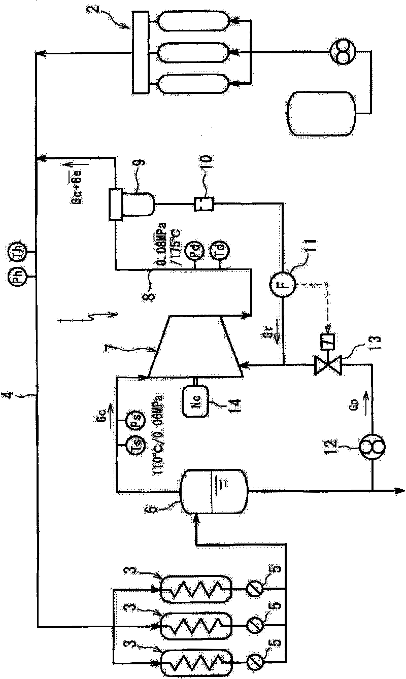
[0018] Embodiments of the present invention will be described below with reference to the drawings. figure 1 The configuration of the manufacturing equipment including the vapor compression device 1 according to the first embodiment of the present invention is shown.

[0019] The vapor compression device 1 is a device that supplies vapor (gas-phase object fluid) at a predetermined supply pressure Ph (for example, 0.8 MPaG) from a boiler 2 to a required facility (manufacturing facility) 3 through a main pipe 4, wherein the suction temperature Ts (for example, 110°C) and low-pressure steam with a mass flow Gc (for example, 1000kg / h) are sucked into the action space of the screw compressor 7 (that is, between a pair of internal and external screw rotors meshing with each other and the housing that accommodates the screw rotors) The space formed between. This space is not directly connected with the suction part and the discharge port of the screw compressor 7), and the pressure i...


PUM


Abstract

A steam compressor arrangement comprises the following components: a positive displacement compressor for compressing the steam which is sucked into a reaction space and is used as a gas phase object fluid and discharging to a discharging tube with a preset discharging pressure; a liquid guiding mechanism for guiding the liquid phase objective fluid into the reaction space or a suction space of the compressor; and a dehydrator which is configured on the discharging tube and separates liquid phase part from the objective fluid discharged from the compressor, wherein, the liquid guiding mechanism guides the liquid phase object fluid with enough amount for the following states: namely, the heat is consumed as latent head of vaporization, which is used for vaporizing the liquid phase object fluid; the heat is the residual heat which is in the energy given from the compressor to the object fluid and is after energy consumption for increasing the pressure of the gas phase object fluid sucked by the compressor to the discharging pressure; and furthermore the object fluid is discharged from the compressor with a state that one part of the object fluid is liquid phase wet steam. Therefore the excessive temperature increase of the compressor is prevented, and the output of the compressor is furthest used as the steam energy.

Description

technical field [0001] The present invention relates to a vapor compression device. Background technique [0002] In the industrial world, there are many devices that use steam, but very few devices can consume its latent heat, and a large amount of steam at 0 MPa and 100 °C is discarded. The following vapor compression device has been proposed: By recovering these discarded low-pressure vapors and compressing them with a compressor, the vapors of usable pressure can be regenerated cheaply with less energy than re-evaporating water by boilers (such as Japan · Special Publication No. 6-70540). [0003] In such a vapor compression device, the discharge pressure of the compressor is also determined based on the set pressure of the main steam piping of the boiler. A compressor having a capacity sufficiently large for the amount and pressure of the compressed vapor is used as the compressor, but excessive output causes an excessive temperature rise of the discharged vapor. Not...

Claims


Application Information

Patent Timeline
IPC IPC(8): F04C29/04F01K17/00
CPCY02A30/274
Inventor 松隈正树桑原英明
Owner KOBE STEEL LTD
Why Eureka
Try Eureka