Pulse combustion control system and control method

A technology of pulse combustion and pulse control, which is applied in the direction of controlling combustion, lighting and heating equipment, and can solve the problems of high price

Active Publication Date: 2010-06-16
BERIS ENG & RES CORP
View PDF0 Cites 31 Cited by
  • Summary
  • Abstract
  • Description
  • Claims
  • Application Information

AI Technical Summary

Problems solved by technology

At present, most of the pulse controllers use the pulse controllers produced by the German KROM / / SCHRODER company, and the price is relatively expensive.

Method used


Image

  • Pulse combustion control system and control method
  • Pulse combustion control system and control method
  • Pulse combustion control system and control method

Examples


Embodiment Construction

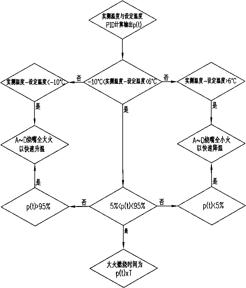
[0021] There are two forms of pulse combustion control, one is large and small fire pulses, and the other is open and close pulses. The procedures used in the two pulse forms are exactly the same. The applicable fuel for pulse control can be natural gas with high calorific value or clean coal gas. In the present invention, the control system adopts large and small fire pulse mode, and the fuel adopts natural gas as an example for illustration.

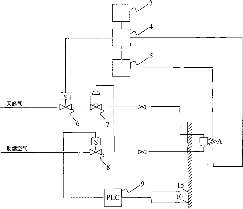
[0022] The pulse control system of the present invention is composed of three parts: ignition, flame monitoring and large and small fire pulse combustion control. The main structure of the system is as follows: figure 1 As shown, including: flame monitoring 3 (computer screen display), burner controller 4, ignition transformer 5, gas solenoid valve 6, air / gas proportional valve 7, air solenoid valve 8, PLC temperature control system 9, temperature detector 10. Temperature detector 15.

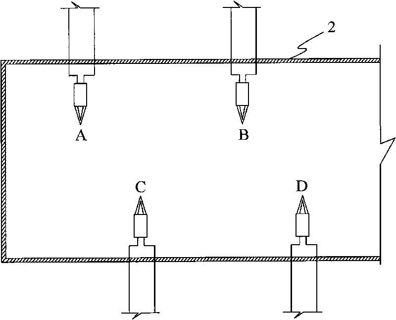
[0023] Each burner is equipped with a set of ig...


PUM


Abstract

The invention provides a method for controlling pulse combustion which uses a Programmable Logic Controller (PLC) programme to replace a pulse combustion controller to achieve the pulse combustion control, and mainly comprises an adjustment step, a nonlinear treatment step and an output step. The pulse combustion control is innovatively achieved through three steps of PLC programme, the nonlinear treatment step and the output. The method not only saves a large number of costs required for buying pulse controllers, but also has the control effect which is more flexible than the control effect of the pulse controllers, and the temperature control accuracy and the uniformity can well meet process requirements.

Description

technical field [0001] The invention relates to a combustion control system and a control method, in particular to a pulse combustion control system and a control method of an industrial kiln. Background technique [0002] The improvement of workpiece heating quality in industrial furnaces is closely related to combustion control technology. At present, proportional control and double-crossing limiter control are generally used in China, but their realization is often restricted by the key link of fuel measurement and adjustment, and there are some disadvantages. In order to overcome the disadvantages of traditional combustion control, a revolutionary pulse combustion control technology has recently appeared in the world. The pulse combustion control technology has been called "the development direction of future industrial furnace control technology". This control system controls the temperature of the furnace by controlling the combustion sequence and combustion time of t...

Claims


Application Information

Patent Timeline
Patent Type & Authority Applications(China)
IPC IPC(8): F23N5/00
Inventor 张燕连
Owner BERIS ENG & RES CORP
Why Eureka
Try Eureka