Novel negative ion refrigerating generator

A negative ion generator technology, applied in the field of new negative ion refrigeration generators, can solve the problems of high cost, small amount of negative ion generation, and limited development

Inactive Publication Date: 2010-06-16
洪旗
View PDF0 Cites 10 Cited by
  • Summary
  • Abstract
  • Description
  • Claims
  • Application Information

AI Technical Summary

Problems solved by technology

Although these two methods eliminate ozone, their development is limit

Method used


Image

  • Novel negative ion refrigerating generator
  • Novel negative ion refrigerating generator

Examples


Embodiment Construction

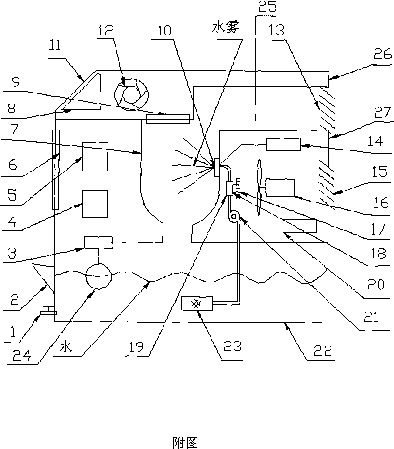
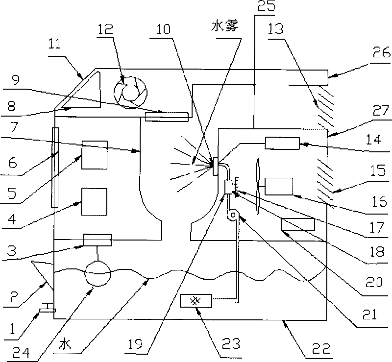
[0008] Spray chamber (7) is hemispherical, is located at the middle part of negative ion generator, and the bottom of spray chamber is connected with water tank, and filter screen (9) is equipped with at the top outlet. Atomization chamber (7), guide vane, exhaust window (11), axial fan (12) is to be made of little plastics to electrostatic adsorption, also can be coated with antistatic paint on its surface. Atomizing nozzle (10 is made of metal and is preferably made of copper material with better electrical conductivity, and the shell of the nozzle is equipped with terminal to be connected with high-voltage power supply (14). The cold surface of semiconductor refrigeration part (18) and the The cold chamber (9) is in contact, and the hot surface is connected with the radiator (17). The blower fan (16) is located near the heat sink (17). The filter screen (9) is made of several layers of pure cotton gauze, and can be equipped with plastic outer frame.

[0009] After the wate...


PUM


Abstract

The invention relates to a novel negative ion refrigerating generator which uses a semiconductor refrigerating device as a cold source and uses water as a substance for absorbing heat and dust and ionizing; by utilizing high-pressure water to generate air negative ions in the process of spray atomization, a domestic electric appliance product which integrates a refrigerating technology and a negative oxide ion generator is produced. The invention has the advantages of various negative ion generators and simultaneously can generate cold air to meet the demands on health care and temperature reduction.

Description

technical field [0001] The invention relates to a refrigeration generator, in particular to a novel negative ion refrigeration generator. It belongs to a household electrical appliance product. Background technique [0002] The negative oxygen ion generators sold in the existing market mostly use a high-voltage electric field to ionize air molecules in the electric field and discharge their tips to obtain a large amount of negative air ions. Due to the use of metal discharge electrode needles, an arc will appear under the action of a high-voltage electric field, so while negative air ions are produced, ozone harmful to the human body is also produced. Another is to use compressed air to absorb water and spray to form negative ions or use the jet effect of pressure water to make water droplets form air negative ions when they split. Though these two kinds of methods have eliminated ozone, because its cost is high, the reason that negative ion generation amount is little has...

Claims


Application Information

Patent Timeline
IPC IPC(8): F24F5/00F25B21/02A61L9/22
Inventor 洪旗
Owner 洪旗
Why Eureka
Try Eureka