
Three-dimensional slab heat pipe with multi-layer microporous pipe arrays and processing technique thereof

A flat heat pipe and processing technology, applied in indirect heat exchangers, lighting and heating equipment, etc., can solve problems affecting the strength and reliability of flat heat pipes, low sealing and reliability performance, limited contact area, etc., to achieve efficiency and The effect of high maximum heat transport capacity and increased heat exchange density

Active Publication Date: 2012-08-01
NANJING ECOWAY ENERGY TECH
View PDF1 Cites 0 Cited by
  • Summary
  • Abstract
  • Description
  • Claims
  • Application Information

AI Technical Summary

Problems solved by technology

Although the flat heat pipe overcomes the disadvantages of the traditional flat heat pipe, because it is a flat heat pipe with a single-layer microporous tube array, the strength and reliability of the flat heat pipe need to be improved, and the contact between the flat heat pipe and the heat exchange object The area is limited, so a heat exchange surface with a limited area is formed between the two, that is, the area of ​​the evaporation section as the heat absorbing part and the area of ​​the condensation section as the heat dissipation part in the flat heat pipe are limited. If you want to improve the local maximum exchange Heat density can only be reduced by reducing the distance between the side-by-side through holes in the flat heat pipe and the diameter of the through hole itself, which will increase the requirements for the extrusion process and affect the strength and reliability of the flat heat pipe
Moreover, in the prior art, the process of sealing the ends of the heat pipes arranged side by side is usually to cover the ends of the heat pipes or put the heat pipes into the sleeve and then weld the sleeve mouth to cover or melt the ends to integrally braze. As a whole, the process is very complicated, and the sealing and reliability performance is low

Method used


Image

  • Three-dimensional slab heat pipe with multi-layer microporous pipe arrays and processing technique thereof
  • Three-dimensional slab heat pipe with multi-layer microporous pipe arrays and processing technique thereof
  • Three-dimensional slab heat pipe with multi-layer microporous pipe arrays and processing technique thereof

Examples


Embodiment Construction

[0043] The present invention will be described below in conjunction with the accompanying drawings.

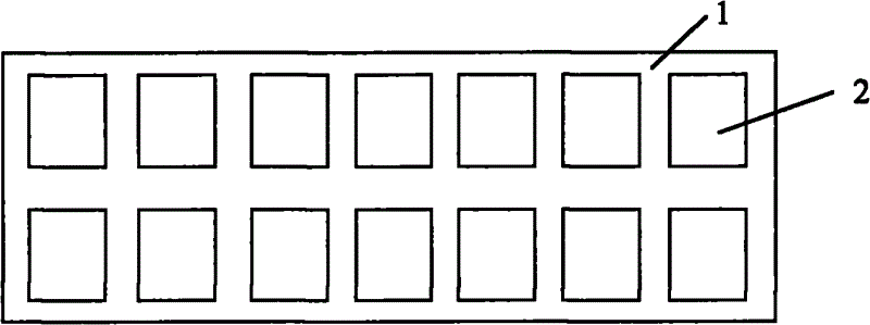
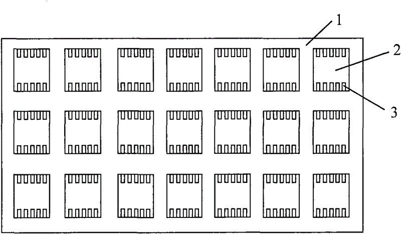
[0044] figure 2 It is a structural schematic diagram of the first embodiment of the three-dimensional flat heat pipe of the present invention, figure 2 The shown three-dimensional flat heat pipe with multi-layer microporous tube arrays includes a heat conductor 1 with two layers of parallel microporous tube arrays formed by extrusion or stamping of metal materials. The heat conductor 1 in this embodiment is Plate-shaped body, each layer of microporous tube arrays includes two or more microporous tubes 2 arranged in parallel, the parallel arranged microporous tubes 2 are parallel to the surface of the plate-shaped body with a wider lateral width, The cross-sectional shape of the channel of 2 is rectangular, and the microporous tube 2 is filled with a liquid working medium to form a micro heat pipe, which transfers heat in the form of phase conversion heat, naturally forming ...


PUM

PropertyMeasurementUnit
thicknessaaaaaaaaaa

Abstract

The invention relates to a three-dimensional slab heat pipe with multi-layer microporous pipe arrays and a processing technique thereof. The three-dimensional slab heat pipe comprises a heat conductor, wherein the heat conductor is formed by extruding or punching metal materials and is provided with two or more than two layers of the microporous pipe arrays arranged in parallel; each layer of themicroporous pipe array comprises two or more than two microporous pipes arranged in parallel; a working medium, which has the functions of phase change and heat transfer, is encapsulated in each microporous pipe; and two ends of the heat conductor are sealed and at least one end head is provided with a gradually-shrinking sealing strip which is formed by cold welding. The three-dimensional slab heat pipe provided by the invention has the advantages of low thermal resistance, high heat-exchanging efficiency, strong bearing capacity and high reliability.

Description

technical field [0001] The invention relates to the technical field of heat exchange, in particular to a three-dimensional flat heat pipe with a multilayer microporous pipe array and a processing technology thereof. Background technique [0002] Compared with the natural convection and forced convection heat transfer methods, due to the high heat transfer efficiency of the phase change heat transfer method, the heat exchanger using the phase change heat technology has been widely used in industry. Among the heater technologies, the most typical one is the heat pipe heat exchanger technology. The main heat transfer mode of the heat pipe is evaporation and condensation, which has the characteristics of large heat transfer capacity, strong temperature control ability, and high heat transfer efficiency. [0003] Traditional heat pipes generally use circular tubes with a certain diameter, and the two ends are closed after filling the working fluid. Compared with other heat pipes,...

Claims


Application Information

Patent Timeline
Patent Type & Authority Patents(China)
IPC IPC(8): F28D15/02F28D15/04B23P15/26
Inventor 赵耀华张楷荣刁彦华
Owner NANJING ECOWAY ENERGY TECH
Learn More