
Method for detecting reflective liquid level displacement based on angular displacement tracking

A reflective, angular displacement technology, applied in the directions of liquid level indicators, electromagnetic wave re-radiation, liquid/fluid solid measurement, etc., can solve the problems of large ultrasonic beam diameter, inapplicability, and influence on accuracy, and achieve a wide range of applications. High practicality and low interference effect

Inactive Publication Date: 2010-06-16
WUHAN TEXTILE UNIV
View PDF0 Cites 21 Cited by
  • Summary
  • Abstract
  • Description
  • Claims
  • Application Information

AI Technical Summary

Problems solved by technology

[0003] One is the measurement of the sensor directly contacting the liquid level. The main problem of this method is that the sensor is relatively easy to affect the original natural state of the measured liquid, and it cannot effectively reflect the actual parameters.
In addition, due to the special adhesion of the liquid surface, for liquids with high viscosity, the interface between the sensor and the liquid is blurred, which affects the accuracy
[0004] The second is the ultrasonic reflection method in the non-contact detection of the sensor, which requires a large reflection area, a large diameter of the ultrasonic beam, and low measurement accuracy; the capacitance detection method is not suitable for the detection of large-capacity and large-volume liquids. Transparent and colorless liquids such as water, alcohol, etc. cannot distinguish the junction of the liquid surface and the air
[0005] In addition, the above-mentioned traditional liquid level detection methods are also greatly affected by environmental conditions and various disturbances, especially in fine detection

Method used


Image

  • Method for detecting reflective liquid level displacement based on angular displacement tracking
  • Method for detecting reflective liquid level displacement based on angular displacement tracking
  • Method for detecting reflective liquid level displacement based on angular displacement tracking

Examples


Embodiment Construction

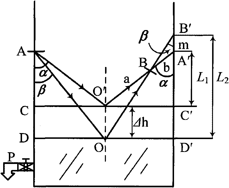
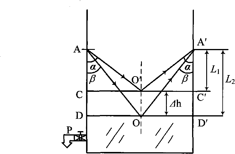
[0018] figure 1 , when the surface of the measured liquid passes through the position C-C', the reflected light of A is projected to point A' by the focusing lens, and the timing and tracking procedures are started by the corresponding circuit. If the value of the initial incident angle α is known, then by According to the trigonometry principle, the initial position of the liquid surface C-C' is:

[0019] L 1 = OC ′ ‾ · cot α

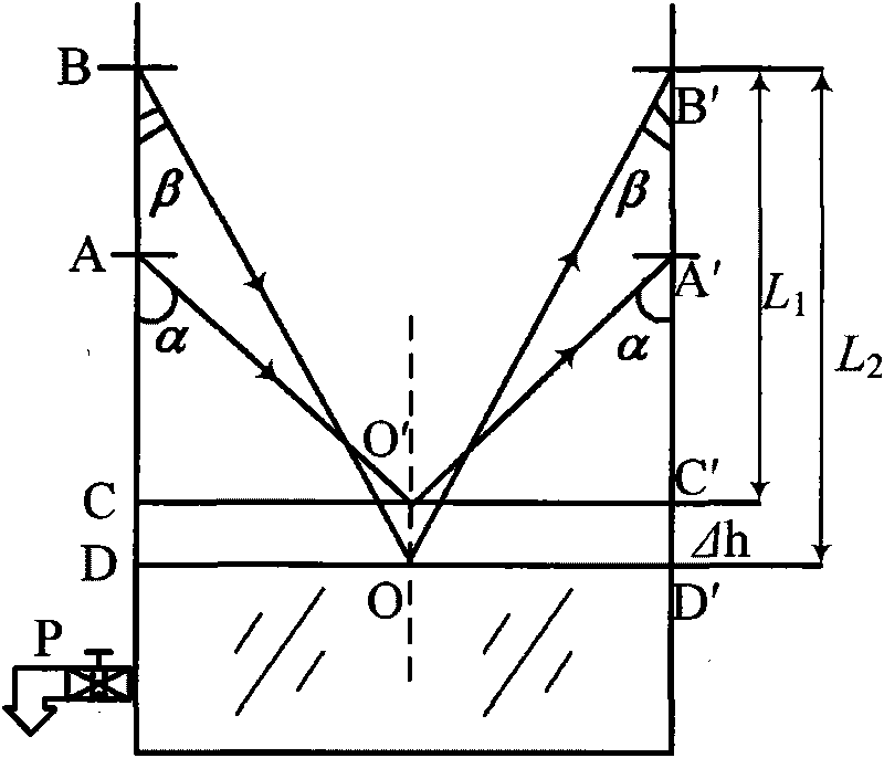
[0020] As the liquid flows out from the P port, the liquid will fall freely, and the emitted light will track and adjust the incident angle. When the liquid level drops to the D-D' position, the reflected light will be projected to the B' point by the lens, and the liquid will be obtained on the vertical detection surface. The imaging m of the surface displacement, after the detection of the photoelectric unit matrix, the ...


PUM


Abstract

The invention relates to a method for detecting reflective liquid level displacement based on angular displacement tracking, which comprises the following steps that: a light-emitting device generates a beam of visible light or invisible light through a group of lenses, and the visible light or the invisible light enters a liquid surface at a certain angle alpha to generate reflected light at the same angle; by using the other group of lenses on a receiver, the reflected light is received by a photoelectric conversion device to form images on a detection surface so as to generate electric signals, and the electric signals are treated by a circuit to determine the initial position of the liquid level as shown in a figure; when the liquid level is displaced, the emitting angle of a light beam is changed continuously in a mode of synchronous tracking to form the angular displacement of emitted light, and a light image track proportioned with the liquid level displacement can be generated on a fixed detection surface; and the distance of the liquid level displacement can be acquired according to the angular displacement through circuit and routine calculation according to a trigonometry theory, and if the time when the displacement happens is recorded at the same time, the speed of the liquid level displacement can be obtained. Because the position of the liquid level and the light beam emitting angle have a one-to-one correspondence relation, when the displacement distance is large, the angles of an emitted light beam and a receiving lens can be simultaneously changed to detect the distance and the speed to the liquid level displacement.

Description

Technical field: [0001] The invention relates to a reflective non-contact non-destructive automatic displacement detection method based on angular displacement tracking, in particular to position and speed detection in liquid Newtonian displacement. Background technique: [0002] Although there are many methods for liquid level displacement measurement so far, they have two defects in summary: [0003] One is the measurement of the sensor directly contacting the liquid level. The main problem of this method is that the sensor is relatively easy to affect the original natural state of the measured liquid, and it cannot effectively reflect the actual parameters. In addition, due to the special adhesion of the liquid surface, for liquids with high viscosity, the interface between the sensor and the liquid is blurred, which affects the accuracy. [0004] The second is the ultrasonic reflection method in the non-contact detection of the sensor, which requires a large reflection ...

Claims


Application Information

Patent Timeline
IPC IPC(8): G01F23/292G01P3/68
Inventor 陶桓齐
Owner WUHAN TEXTILE UNIV
Learn More