Developing method and developing apparatus

A developing method and technology for developing equipment, which are applied to equipment, instruments, optics and other directions of an electrical recording process applying charge patterns, can solve the problem of reducing yield, contaminating laser sources and photodetectors, and cutting off monitoring signal parts that are time-consuming. problem, to achieve the effect of improving the control accuracy

Inactive Publication Date: 2010-06-16
SONY DISC & DIGITAL SOLUTIONS INC
View PDF5 Cites 1 Cited by
  • Summary
  • Abstract
  • Description
  • Claims
  • Application Information

AI Technical Summary

Problems solved by technology

In order to perform monitoring, the developer on the monitor signal portion must be removed by nitrogen blowing, and a time-consuming excision step of cutting the monitor signal portion must be performed separately, thereby reducing the yield
Also, since the degree of development progress at the monitor signal portion is different from that of the signal area, precise development cannot be performed
In addition, it is necessary to prevent nitrogen blowing from affecting the development of the signal area, because nitrogen blowing will cause smoke to spread and contaminate laser sources and photodetectors, etc.

Method used


Image

  • Developing method and developing apparatus
  • Developing method and developing apparatus
  • Developing method and developing apparatus

Examples


no. 1 example

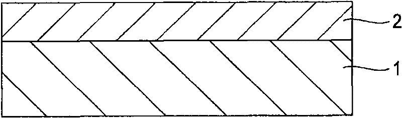
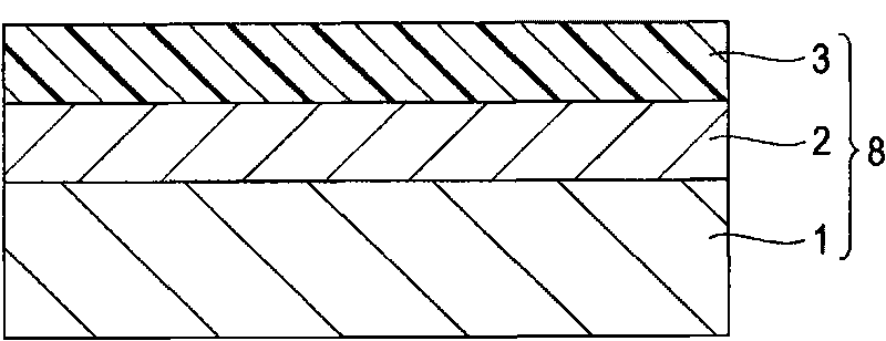
[0052] Figure 5A is the first embodiment of the present invention for the development step (such as Figure 2D and 2E Schematic side view of the developing device in ). Figure 5B is a schematic plan view of the developing device. In this first embodiment, the resist substrate 8 to be developed has a latent image constituted by the exposed portion 3a, and the track pitch of BD is 0.32 μm.

[0053] like Figure 5A and 5B As shown, the developing device 15 of the first embodiment includes a rotatable turntable 10 and a nozzle 12 for supplying a developer 13 . The developing device 15 also includes a laser light source 11 for emitting laser light L for monitoring, and zero-order light (reflected light) L for detecting reflected laser light L. 0 The amount of light the first sensor R 0 and primary light (diffracted light) L for detecting reflected laser light L 1 The second sensor R of the amount of light 1 .

[0054] The turntable 10 is coupled to the rotation shaft 10...


PUM

PropertyMeasurementUnit
wavelengthaaaaaaaaaa

Abstract

The invention provides a developing method and a developing apparatus. A developing method includes the steps of setting a resist substrate on a turntable, the resist substrate including a substrate, an inorganic resist layer formed on the substrate, and a latent image formed by exposure to light; discharging developer to a developer application position on an upper surface of the inorganic resist layer while rotating the turntable, the developer application position being away from the center of the resist substrate; irradiating a monitor position on the upper surface of the inorganic resistlayer with laser light, the monitor position being different from the developer application position; and continuously discharging the developer, while detecting the amounts of zeroth order light andfirst order light reflected by the upper surface of the inorganic resist layer and monitoring the light amount ratio of the first order light to the zeroth order light, until the light amount ratio becomes a predetermined value.

Description

technical field [0001] The invention relates to a developing method and a developing device for manufacturing an original disc. Background technique [0002] As for optical discs for data storage media, various formats including CDs and DVDs have been proposed according to their uses. The disc substrates used in each format are usually made by injection molding of polymer materials. On the surface of the substrate, a convex-concave pattern including pits and grooves is formed. [0003] A concavo-convex pattern including pits and grooves formed on the optical disc substrate represents a data signal. By making the convex-concave pattern fine and dense, the capacity of the optical data storage medium can be increased. [0004] A concave-convex pattern including pits and grooves is formed on the optical disc substrate by transferring the concave-convex pattern formed on the master optical disc to the optical disc substrate. An original optical disc having a concavo-convex pa...

Claims


Application Information

Patent Timeline
Patent Type & Authority Applications(China)
IPC IPC(8): G03F7/30G11B7/26
CPCG03G13/286G03G15/043G03G15/326G03G2215/00523G03G15/04072G03G15/6591
Inventor 青木忠久
Owner SONY DISC & DIGITAL SOLUTIONS INC
Why Eureka
Try Eureka