Radiator optimally designed according to wind speeds in flow fields

A radiator and optimized technology, applied in cooling/ventilation/heating transformation, instruments, calculations, etc., can solve the problem of high wind shear noise, and achieve the effect of reducing wind shear noise, good heat dissipation effect, and increasing heat dissipation area

Inactive Publication Date: 2010-06-16
INVENTEC CORP
View PDF0 Cites 9 Cited by
  • Summary
  • Abstract
  • Description
  • Claims
  • Application Information

AI Technical Summary

Problems solved by technology

[0005] The invention provides a heat sink optimized with the wind speed

Method used


Image

  • Radiator optimally designed according to wind speeds in flow fields
  • Radiator optimally designed according to wind speeds in flow fields
  • Radiator optimally designed according to wind speeds in flow fields

Examples


Embodiment Construction

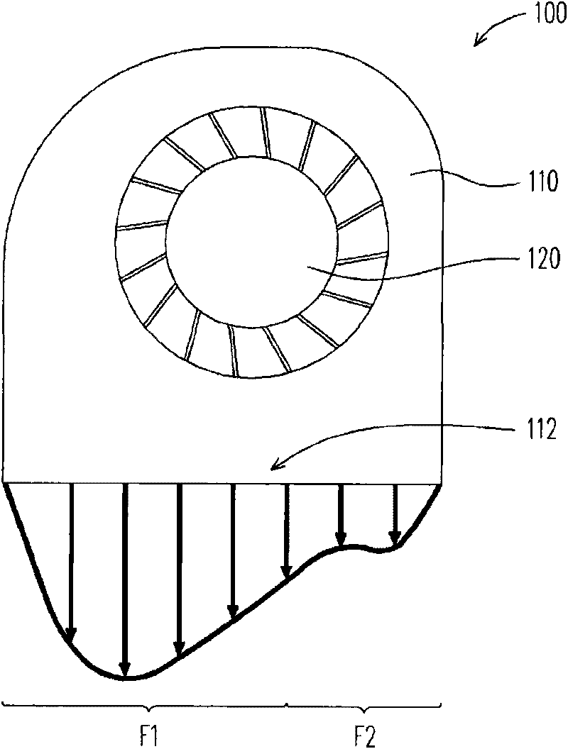
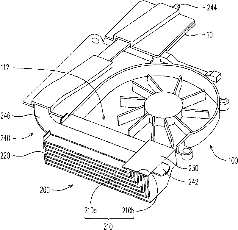
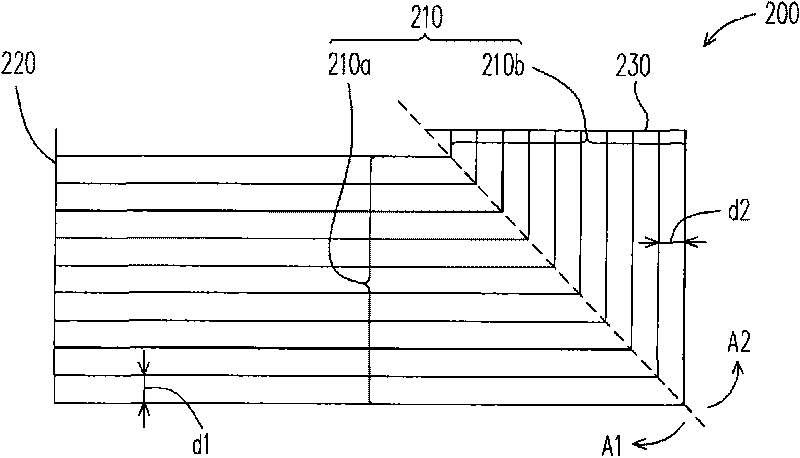
[0031] In order to avoid the problem of excessive wind shear noise or poor heat dissipation effect caused by insufficient heat dissipation area when the airflow passes through the traditional radiator, the present invention optimizes the design of the radiator of the present invention. By arranging cooling fin groups of different structures at the air outlet of the fan to correspond to the flow field areas of different wind speeds, the effect of reducing wind shear noise and increasing the heat dissipation area is achieved. In other words, the radiator of the present invention is suitable to be arranged at the air outlet of a fan, and has the characteristic of being optimally designed according to the wind speed in the flow field area. The following examples will illustrate the present invention, but they are not intended to limit the present invention. Those skilled in the art can make appropriate modifications to the following examples according to the spirit of the present i...


PUM


Abstract

The invention discloses a radiator optimally designed according to the wind speeds in flow fields, which is suitable to be arranged at the air outlet of a fan. The radiator comprises a plurality of fins which are formed by connecting a horizontal fin group in a first radiation zone and a vertical fin group in a second radiation zone. The air flow generated by the fan passes through the first radiation zone and the second radiation zone in form of a first flow field and a second flow field, wherein the wind speed of the first flow field is higher than that of the second flow speed.

Description

technical field [0001] The present invention relates to a heat sink, and in particular to a heat sink designed optimally with the wind speed of the flow field. Background technique [0002] In recent years, with the rapid development of computer technology, the operating speed of the computer has gradually increased, and the heating power of the electronic components inside the computer body has also continued to increase. In order to prevent the electronic components inside the computer body from overheating, resulting in temporary or permanent failure of the electronic components, the heat sink has become one of the indispensable devices in the electronic device. [0003] Taking a notebook computer as an example, generally speaking, a fan is installed inside the body of the notebook computer, and a radiator connected to the electronic components is provided outside the air outlet of the fan. The airflow generated by the fan can remove the heat conducted from the electroni...

Claims


Application Information

Patent Timeline
IPC IPC(8): G06F1/20H05K7/20
Inventor 王锋谷王少甫黄庭强许圣杰陈群鹏
Owner INVENTEC CORP
Why Eureka
Try Eureka