Connector and light source device

A light source device and connector technology, which is applied in the directions of connection, coupling device, lighting device, etc., can solve the problems of difficult parallelism of electrode columns, low yield rate, and electrode column falling off, so as to improve the manufacturing yield and quality. The effect of high yield and high reliability

Inactive Publication Date: 2011-08-31
EVERLIGHT ELECTRONICS
View PDF0 Cites 0 Cited by
  • Summary
  • Abstract
  • Description
  • Claims
  • Application Information

AI Technical Summary

Problems solved by technology

However, the fixture itself does not have the effect of conducting electricity, but only has the effect of fixing the lamp tube, so additional wires are needed to electrically connect the circuit board in the lamp tube and the lamp holder
The additional wires must be manually soldered to connect the circuit board and the lamp holder in the lamp tube, which will make the installation and disassembly of the LED lamp tube difficult, resulting in difficult and time-consuming replacement of the lamp tube
[0004] If in order to solve the problem of difficult installation and disassembly of the above-mentioned light-emitting diode lamp tube, the two electrode columns suitable for being inserted into the socket of the lamp socket of the traditional fluorescent lamp are directly welded on the circuit board by welding, and there will be structural strength. Insufficient and the parallelism of the two electrode columns is not high enough
Specifically, when the electrode column of the LED tube is inserted into the socket of the lamp socket in a manner similar to that of installing a traditional fluorescent tube, and the LED tube is rotated to the position, the torque of the rotating tube will easily make the electrode column and the circuit The solder joints between the boards can't bear it, causing the electrode post to fall off the circuit board
In addition, it is quite difficult to maintain the parallelism of the two electrode columns during the welding process, so this design method is likely to lead to low yield

Method used


Image

  • Connector and light source device
  • Connector and light source device
  • Connector and light source device

Examples


Embodiment Construction

[0046] In order to make the above-mentioned features and advantages of the present invention more comprehensible, the following specific embodiments are described in detail with reference to the accompanying drawings.

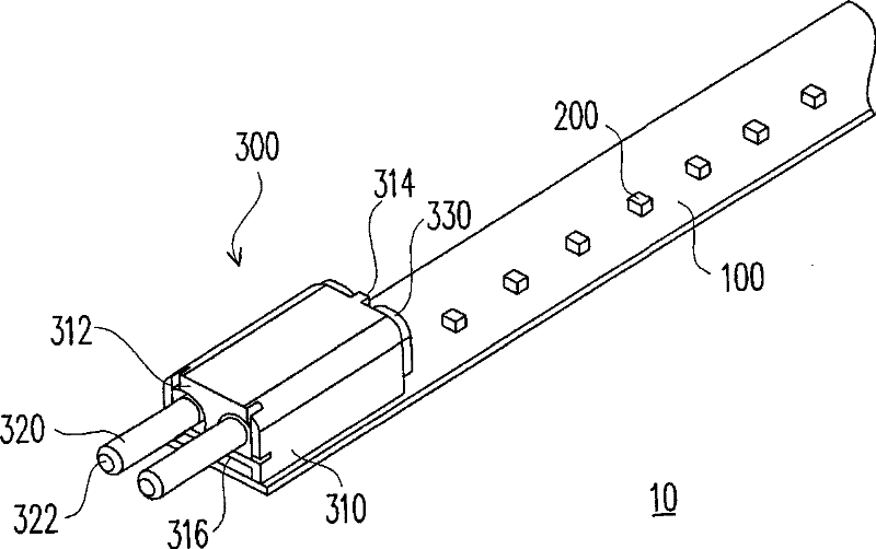
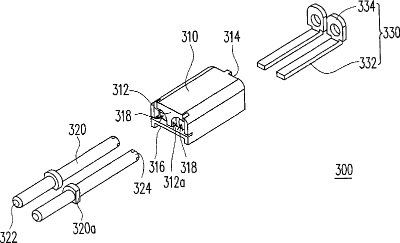
[0047] figure 1 is a schematic diagram of a light source device according to an embodiment of the present invention. figure 2 for figure 1 An exploded view of the connector in the light source unit. Please refer to figure 1 and figure 2 The light source device 10 includes a carrier board 100 , a plurality of light emitting elements 200 and a connector 300 , wherein the light emitting elements 200 and the connectors 300 are all configured on the carrier board 100 . In this embodiment, the light emitting element 200 is, for example, a light emitting diode. The connector 300 includes an insulating seat 310 , two electrode columns 320 and two L-shaped electrode pieces 330 . The insulating seat 310 has a first side surface 312 , a second side surface 314 , a...


PUM


Abstract

The invention relates to a connector comprising an insulating seat, two electrode posts and two L-shaped electrode slices, wherein the insulating seat is provided with a first side surface, a second side surface opposite to the first side surface, a lower surface for connecting the first side surface with the second side surface and two through holes, and the two through holes penetrate through the insulating seat and extend to the second side surface from the first side surface; the two electrode posts respectively penetrate through the two through holes, each electrode post is provided witha first end and a second end which are opposite to each other, and the first end protrudes the first side surface; each L-shaped electrode slice comprises a bottom arranged on the lower surface and aconnecting part connected to the bottom, and the connecting parts are arranged on the second side surface and are respectively connected to the second ends of the electrode posts.

Description

technical field [0001] The present invention relates to a connector, and in particular to a connector used for electrical connection. Background technique [0002] With the advancement of semiconductor technology, the power that can be achieved by light-emitting diodes (light-emitting diodes, LEDs) is getting higher and higher, and the intensity of the emitted light is getting higher and higher. In addition, light-emitting diodes also have the advantages of power saving, long service life, environmental protection, fast start-up, and small size. Therefore, light-emitting diodes are also widely used in lighting equipment, traffic signs, monitors, optical mice and other products, and there is a tendency to gradually replace traditional fluorescent tubes. [0003] In order to fix the LED lamp tube on the lamp holder of the traditional fluorescent lamp tube, a prior art is to fix the LED lamp tube on the lamp holder by using a fixing piece. However, the fixing member itself ha...

Claims


Application Information

Patent Timeline
Patent Type & Authority Patents(China)
IPC IPC(8): H01R33/94F21V23/06
Inventor 陈奕宏刘玉茹裴建昌
Owner EVERLIGHT ELECTRONICS
Why Eureka
Try Eureka