Ultrasonic gas cyclone condensing and separating device

A condensation separation and supersonic technology, which is applied in the fields of natural gas dehydration and heavy hydrocarbon separation, can solve the problems of vortex dissipation of rotating gas, easy generation of shock waves, and reduced pressure recovery performance of devices, so as to reduce the impact of separation efficiency and reduce Radial velocity gradient, the effect of reducing energy loss

Inactive Publication Date: 2010-06-23
文闯
View PDF8 Cites 24 Cited by
  • Summary
  • Abstract
  • Description
  • Claims
  • Application Information

AI Technical Summary

Problems solved by technology

The entry of natural gas containing saturated water into the pipeline often causes a series of problems: (1) increase the power consumption of pipeline transportation and reduce the gas transmission volume; (2) CO in natural gas 2 and H 2 S dissolved in free water will form acid and corrode pipelines and equipment; (3) The hydrate crystallization formed by water and natural gas causes the local accumulation of natural gas hydrate, which reduces the cross-sectional area of ​​the gas transmission pipeline, reduces the gas transmission volume, and affects the stable gas supply , which can block gas pipelines and other processing equipment in severe cases; (4) the presence of heavy hydrocarbons will also reduce the calorific value of natural gas, reduce gas transmission efficiency, and block pipelines in severe cases
The device installs delta wings in the supersonic section to generate strong swirling flow, but it is easy to generate shock waves, resulting in instability of the condensation flow field and reducing the pressure recovery performance of the device
U.S. Patent US 6372019 B1 installs a swirl generator before the Laval nozzle to make the gas rotate before accelerating. The shock wave in the device is easy to control, but vortex dissipation tends to occur after the rotating gas enters the Laval nozzle, which reduces the separation efficiency
Chinese patent ZL 200520111901, application number 200610043158.2 and application number 200810224499.9 also have the problem that rotating gas is prone to eddy dissipation

Method used


Image

  • Ultrasonic gas cyclone condensing and separating device
  • Ultrasonic gas cyclone condensing and separating device
  • Ultrasonic gas cyclone condensing and separating device

Examples


Embodiment Construction

[0021] The structural features and working principle of the present invention will be further described in detail below in conjunction with the accompanying drawings.

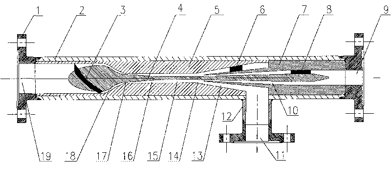
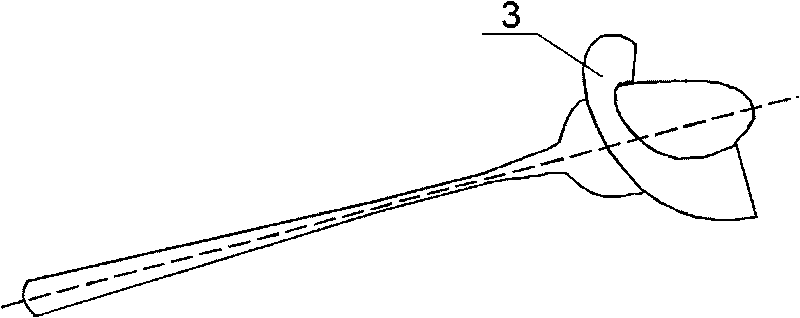
[0022] For the technical scheme of the present invention, see figure 1 , The supersonic gas cyclone condensation separation device is mainly composed of flange 1, shell 2, spiral swirl blade 3, inner core 4, shrink separation shell 5, liquid guide vane 6, diffuser casing 7, guide vane 8 , The drain pipe 12 is composed. Among them, the inner core 4 and the shrinking and separating shell 5 form an annular Laval nozzle, forming a subsonic shrinking flow channel 18, a throat 17, and a supersonic expansion flow channel 16; the inner core 4 and the diffuser shell 7 form an annular diffuser The tube forms a diffuser flow passage 10; the gap between the shrinkage separation shell 5 and the diffuser shell 7 forms a liquid separation port 14 and a liquid accumulation cavity 13.

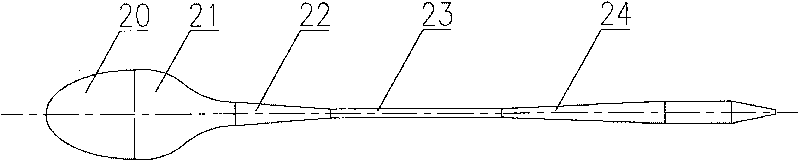
[0023] See figure 1 , 2 , The inner core 4 of...


PUM

PropertyMeasurementUnit
thicknessaaaaaaaaaa
angleaaaaaaaaaa
angleaaaaaaaaaa

Abstract

The invention relates to an ultrasonic gas cyclone condensing and separating device applied to the field of gas purification, in particular to the field of natural gas dewatering and heavy hydrocarbon separation. Natural gas generates a cyclone by spiral cyclone blades, enters an Laval nozzle to adiabatically expand to an ultrasonic velocity and form low temperature and low pressure so that water and heavy hydrocarbon in the natural gas are condensed into liquid drops; meanwhile, a higher tangential velocity is generated to fling the water and the heavy hydrocarbon which are condensed to the wall surface under the action of a strong cyclone field; liquid flows into a liquid-collecting cavity from a liquid shunt hole and is discharged from a liquid outlet by a liquid-discharging pipe; and dry gas enters a circular diffuser pipe, is recovered by pressure and is discharged from a dry gas outlet. The shrinking section of the Laval nozzle of the device is designed by using a bicubic curve method to reduce flowing loss; the spiral cyclone blades can enhance the cyclone, generate greater tangential velocity and have good enhance effect. The device has simple structure, easy process and stable and reliable operation without movable parts.

Description

Technical field [0001] The invention relates to a set of supersonic gas cyclone condensation separation device, which is mainly used in the fields of gas purification, especially natural gas dehydration and heavy hydrocarbon separation. Background technique [0002] At present, most of my country's natural gas resources are condensate gas fields and sour gas fields, and their development is relatively late. The gas flow from the wellhead of the natural gas field is almost saturated with water vapor and contains a small amount of heavy hydrocarbons. The entry of natural gas saturated with water into the pipeline often causes a series of problems: (1) Increase the power consumption of pipeline transportation and reduce the gas transmission; (2) CO in natural gas 2 And H 2 S dissolves in free water to form acid, corroding pipelines and equipment; (3) The hydrate crystallization formed by water and natural gas causes the local accumulation of natural gas hydrate to reduce the cross-s...

Claims


Application Information

Patent Timeline
Patent Type & Authority Applications(China)
IPC IPC(8): B01D5/00B01D45/16
Inventor 文闯曹学文
Owner 文闯
Why Eureka
Try Eureka