Incubation chamber and wrapped moving incubation device

An incubator and incubator technology, applied to laboratory appliances, shells or chambers, heating or cooling equipment, etc., can solve the problems of temperature difference, inconvenient use, inconsistent reaction, etc., to avoid heat loss, Guarantee the effect of accuracy and stability

Inactive Publication Date: 2010-06-23
河北质康医疗器械科技有限公司
View PDF0 Cites 6 Cited by
  • Summary
  • Abstract
  • Description
  • Claims
  • Application Information

AI Technical Summary

Problems solved by technology

[0002] In modern medical testing, in the process of analyzing blood and other human body fluids or secretions, many of them need to be carried out in an environment close to the human body, which requires a constant temperature incubation device. Many instruments need to be equipped with a constant temperature water bath box to allow the reaction After the reaction is completed, take it out for detection. The constant temperature water bath is relatively large in size and inconvenient to use, and the detection process cannot be fully automated; the constant temperature of existing automatic instruments is mainly achieved by heating a relatively closed space. Realized, this can achieve a certain effect, but there will be temperature differences in different parts of the closed space, and the temperature differences will cause inconsistencies in the reactions everywhere, which in turn affects the accuracy and repeatability of the results
Moreover, the constant temperature device on the existing automatic instrument is processed in batches. A batch of reaction cups enter the incubation room. The cuvettes are not saturated, and you have to wait for the previous batch to be incubated before entering. It is impossible to flexibly adjust the cuvettes that require a single test according to the actual situation.

Method used


Image

  • Incubation chamber and wrapped moving incubation device
  • Incubation chamber and wrapped moving incubation device
  • Incubation chamber and wrapped moving incubation device

Examples


Embodiment Construction

[0033] The present invention will be further described in detail below in conjunction with the accompanying drawings.

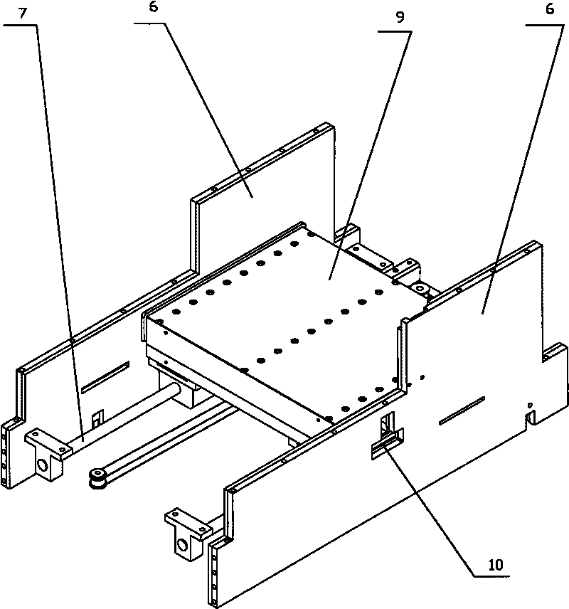
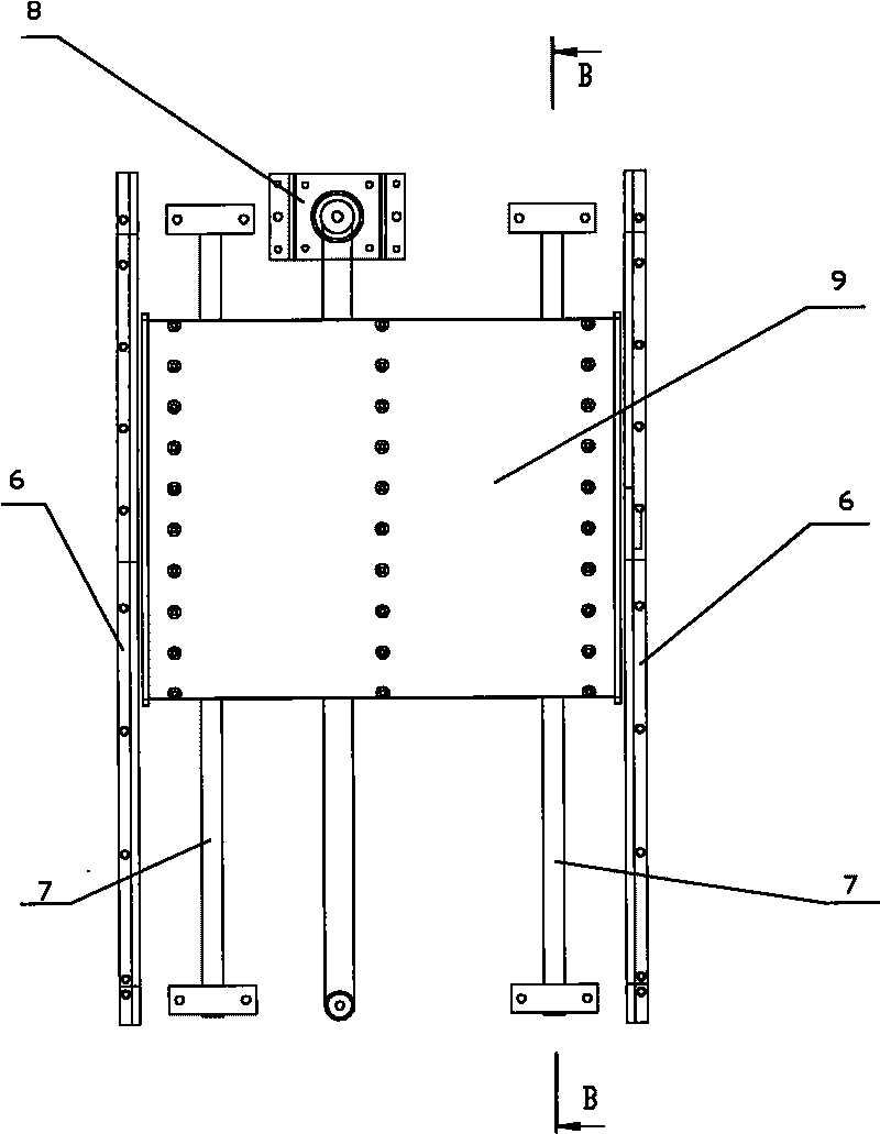
[0034] The containment movement type incubation device of the present invention comprises an incubation chamber 9 and guide rail 7, and described incubation chamber 9 can move along guide rail 7, and incubation chamber 9 of the present invention is connected with synchronous motor 8, and guide rail 7 is arranged on the bottom of incubation chamber 9, by The synchronous motor 8 drives the incubation chamber 9 to move on the guide rail 7 . Therefore, exercise is added while incubating, so that the contents of the cuvette can be fully contacted and the reaction is more complete.

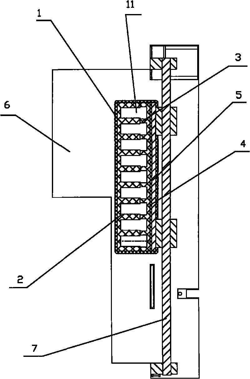
[0035] The incubation chamber 9 of the present invention includes an incubation tray 3 for placing a reaction cup 11, an electric heating film 4 located under the incubation tray 3, an incubation cover plate 2 on the reaction cup 11 and an external insulation layer 1, an incubation tra...


PUM


Abstract

The invention relates to an incubation chamber and a wrapped moving incubation device, belonging to the field of full-automatic medical detection instrument. The incubation chamber comprises an incubation disc for holding a reaction cup, an electric heating membrane arranged below the incubation disc, a cover board arranged on the reaction cup and an external insulation layer. The incubation chamber is characterized in that the incubation disc and the cover board are aluminium plates provided with a plurality of long grooves; the incubation disc and the cover board are buckled with each other in a reverse direction so that the grooves can correspond with each other and the edges of the grooves can contact with each other; and the reaction cup is arranged in an incubation channel formed by the two grooves. The temperature of each part of the incubation chamber is similar, thus ensuring stability of the temperature and ensuring detection accuracy. The space of the whole incubation chamber is divided into a plurality of relatively independent incubation channels by the wrapped moving incubation device; reaction cups with different incubation time can be placed in different incubation channels so that the reaction cups can get in and out of the incubation chamber through the inlet and the outlet of a thermal insulation baffle, and the reaction cups on the same incubation channel can be controlled seperately.

Description

technical field [0001] The invention relates to a constant temperature device, in particular to a constant temperature incubation device used in an automatic medical inspection process. Background technique [0002] In modern medical testing, in the process of analyzing blood and other human body fluids or secretions, many of them need to be carried out in an environment close to the human body, which requires a constant temperature incubation device. Many instruments need to be equipped with a constant temperature water bath box to allow the reaction After the reaction is completed, take it out for detection. The constant temperature water bath is relatively large in size and inconvenient to use, and the detection process cannot be fully automated; the constant temperature of existing automatic instruments is mainly achieved by heating a relatively closed space. Realized, this can achieve a certain effect, but there will be temperature differences in different parts of the ...

Claims


Application Information

Patent Timeline
IPC IPC(8): B01L7/00B01L1/00
Inventor 赵作永
Owner 河北质康医疗器械科技有限公司
Why Eureka
Try Eureka