Jigsaw blade for hand-held power jigsaws

A technology for reciprocating saws and piercing saw blades, applied in the field of reciprocating saw blades, can solve problems such as clamping end damage, and achieve the effects of increasing bending load, improving cutting efficiency, and improving cutting efficiency and cutting quality.

Active Publication Date: 2010-06-23
ROBERT BOSCH GMBH
View PDF4 Cites 6 Cited by
  • Summary
  • Abstract
  • Description
  • Claims
  • Application Information

AI Technical Summary

Problems solved by technology

In the case of long saw blades this can lead to damage especially to the clamping end, thus leading to premature failure of the saw blade

Method used


Image

  • Jigsaw blade for hand-held power jigsaws
  • Jigsaw blade for hand-held power jigsaws
  • Jigsaw blade for hand-held power jigsaws

Examples


Embodiment Construction

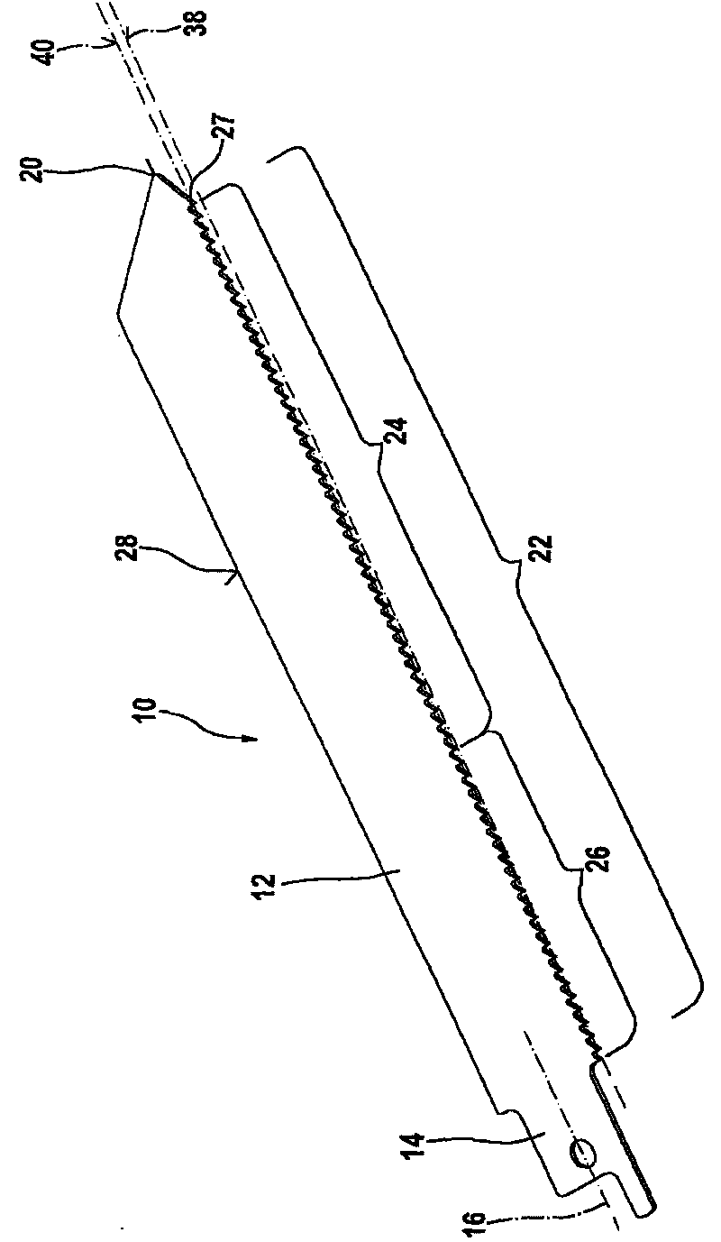
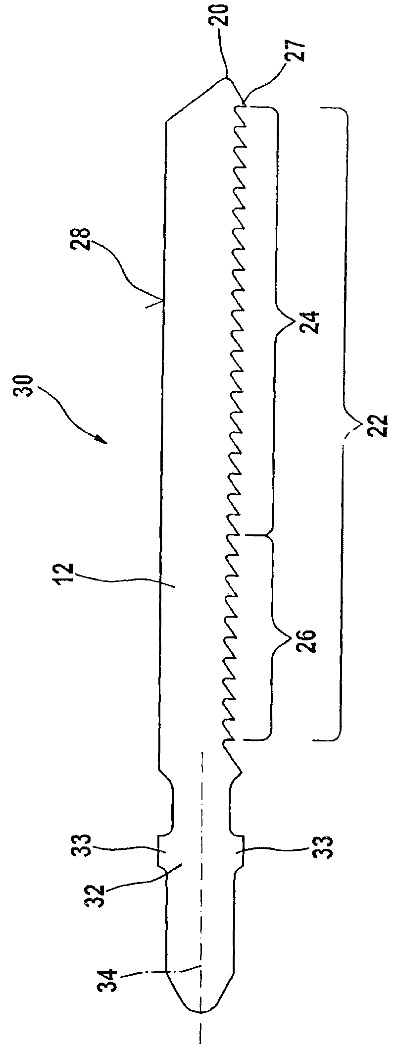
[0022] exist figure 1 The saw blade 10 for a saber saw according to the invention shown in the figure comprises a longitudinal, flat, blade-like working body 12 which has a clamping end 14 at the rear and a saw blade at the front Tip 20. The clamping end 14 has a central axis 16 and is smaller in width than the working body 12 , so that it is relatively sensitive to large bending moments in the plane of the saw blade 10 . A rearwardly extending tooth row 22 adjoins the saw blade tip 20 on the lower plane side. The saw blade back 28 extends on the rear or top plane side of the working body 12 .

[0023] In this case, the first tooth row region 26 of the tooth row 22 , which directly adjoins the clamping end 14 , is inclined at a positive angle of approximately 5° relative to the axis 16 of the clamping end 14 in the rearward viewing direction. The inclined dentition zone 26 occupies approximately ⅓ of the length of the dentition 22 and transitions into a further dentition zo...


PUM


Abstract

A jigsaw blade (10) having a clamping end (14) and, adjoining it, a blade-like working body (12) that has a row (22) of saw teeth that is inclined in relation to the clamping end (14,32), a spine (28) on the opposite side from the row (22) of teeth, and a tip (20) at the front is therefore safer, easier to use, has higher performance, and is more precise. The jigsaw blade (10) has two tooth row regions (24,26) of the row (22) of saw teeth that are inclined at different angles in relation to the clamping end (14).

Description

technical field [0001] The present invention relates to a reciprocating saw blade for a hand-held reciprocating saw machine. Background technique [0002] Reciprocating saw blades are known, the tooth rows of which are inclined at an angle relative to the gripping end in the direction of feed. Due to this angle of inclination, the tooth row bites into the workpiece to be processed progressively during an upwardly or backwardly directed working stroke. During the working stroke of the saw blade, each tooth of the tooth row which comes into contact with the workpiece penetrates into the workpiece with increasing cutting depths. This results in the desired, progressive cutting behavior when using such saw blades for reciprocating sawing. With the return or idle stroke pointing downwards or forwards, the saw blade is immediately lifted and unloaded from the workpiece due to the inclined tooth row. Compared to conventional saw blades, there is less heat or better cooling, ther...

Claims


Application Information

Patent Timeline
Patent Type & Authority Applications(China)
IPC IPC(8): B23D61/12B23D49/16
CPCB23D61/128Y10T83/935Y10T83/9367B23D61/121B23D49/12B23D61/123
Inventor D·格罗利蒙德
Owner ROBERT BOSCH GMBH
Why Eureka
Try Eureka