Film coating device and film coating method

A coating device and coating technology, applied in printing and other directions, can solve the problems of longer reset time, repeated occurrence of bad defects, and inability to coat, and achieve the effect of narrowing the nozzle spacing

Active Publication Date: 2010-06-23
ISHII HYOKI
View PDF6 Cites 6 Cited by
  • Summary
  • Abstract
  • Description
  • Claims
  • Application Information

AI Technical Summary

Problems solved by technology

[0011] In the case of the flexographic printing method, the pattern formation of the alignment film is easy and the productivity is high, but on the contrary, there are the following problems: 1) In the case of dust adhering to the surface of the relief plate, the alignment film material is not coated on the transparent substrate 2) the amount of alignment film material used is large, 3) when the device is stopped due to a failure, it is necessary to unlock (アニロック) and clean the relief plate, etc., so the reset time becomes longer and the operating rate of the device 4) It cannot be coated on substrates with large unevenness or substrates with curved surfaces
(3) It is necessary to simplify the liquid supply piping of the print head
[0036] In addition to the above, if the piping of each print head on the moving side is complicated, multiple liquid supply control devices must be installed on the print head side, and the weight increases accordingly, and their control also becomes complicated.

Method used


Image

  • Film coating device and film coating method
  • Film coating device and film coating method
  • Film coating device and film coating method

Examples


no. 1 approach

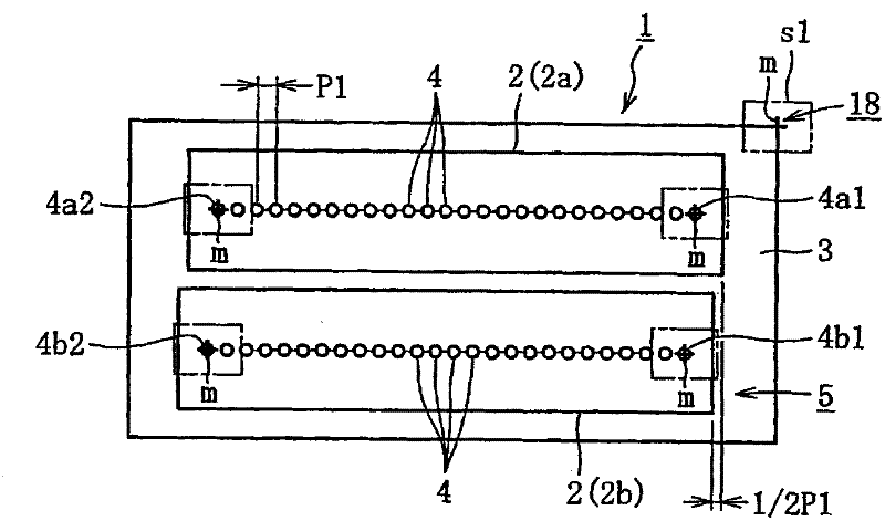
[0101] Figure 1 to Figure 6 The first embodiment of the present invention will be illustrated. The inkjet head 1 described in the first embodiment, such as figure 1 As shown, it consists of two linear inkjet nozzles 2a, 2b and a housing 3 for installing the linear inkjet nozzles 2a, 2b.

[0102] The linear inkjet nozzles 2a and 2b are arranged in a row at predetermined intervals, and the nozzles 4 which discharge the liquid material are arranged in a row. Since the linear inkjet nozzles 2a and 2b mold the nozzles 4 simultaneously during molding, the shape and position of each nozzle 4 can be manufactured with high precision. In addition, the linear inkjet nozzles 2a and 2b supply liquid material to each nozzle 4 from respective liquid material supply parts (not shown), and based on an ejection command signal from a control device (not shown), at a predetermined timing Spray liquid material. Thereby, the linear inkjet nozzles 2a and 2b can discharge the liquid material fr...

no. 2 approach

[0154] Figure 7 ~ Figure 11 The second embodiment of the present invention will be illustrated. The ejection abnormality detecting device 1 of the inkjet head described in the second embodiment is, for example, Figure 7 and Figure 8 As shown in (a), by the camera 5 that photographs the liquid material 4 ejected from the nozzle 3 of the inkjet head 2; the light source 6 that irradiates the light required for photographing; processing the image photographed by the camera 5, thereby detecting ejection abnormalities The ejection abnormality detection part 7 is constituted. Moreover, in this embodiment, if Figure 7 As shown, the inkjet head 2 has a structure in which a single inkjet head 2a in which the nozzles 3 are arranged in series is arranged in a zigzag manner in a longitudinal direction with different positions shifted from each other.

[0155] Camera 5 such as Figure 7 As shown, from the direction perpendicular to the ejection direction of the inkjet head 2, the l...

no. 3 approach

[0182] Figure 13 ~ Figure 17 The third embodiment of the present invention will be illustrated. The film forming apparatus according to the third embodiment, such as Figure 13 As shown, an inkjet head 10 , a film thickness setting unit 20 , a film thickness data storage unit 30 , a gradation profile generation unit 40 , and a film forming unit 50 are provided.

[0183] In this embodiment, the inkjet head 10 is formed by forming line type inkjet nozzles 12 arranged in a row with nozzles 11 for ejecting liquid materials so that the positions of the nozzles 11 are shifted from each other by half the pitch 1 / 2Pn of the nozzle pitch Pn. One inkjet nozzle unit 13 arranged side by side in a parallel manner, and in a staggered manner along the direction of the nozzle 11 provided with the linear inkjet nozzle 12, the positions are staggered differently from each other, and the inkjet nozzle unit 13 is arranged in series. .

[0184] In this inkjet head 10 , line type inkjet nozzles...


PUM


Abstract

The present invention relates to a film coating device and a film coating method. The film coating device utilizes an ink-jet printer to form films on the surfaces of objects to be coated with coating liquid. The film coating device is provided with a print head unit capable of moving on the surfaces of objects to be coated along the first direction. For the print head unit, a plurality of print heads are successively arranged in a direction perpendicular to the first direction across the whole coating width.

Description

[0001] This application is a divisional application based on the patent application with the application number 200580051399.5, the title of the invention is "Inkjet Head and Its Ejection Abnormal Detection Method, and Film Forming Method", and the filing date is August 24, 2005. technical field [0002] The present invention relates to an inkjet head, an inkjet head discharge abnormality detection method and its device for detecting discharge abnormality of the inkjet head, and a film forming method (film coating method) using the inkjet head and its device . Background technique [0003] In recent years, when printing with ink on printing media such as paper, when forming an alignment film and applying UV ink on a substrate (transparent substrate) such as a liquid crystal display, or on a substrate of an organic EL display When coating a color filter, the so-called inkjet method using an inkjet head is widely used. [0004] For example, Japanese Patent No. 3073493 disclos...

Claims


Application Information

Patent Timeline
Patent Type & Authority Applications(China)
IPC IPC(8): B41J2/135B41J2/175B41J2/12
Inventor 中野辉幸小泽康博
Owner ISHII HYOKI
Why Eureka
Try Eureka