Windmill with relative shift between vane and rotation axis
A technology of rotating shafts and blades, applied in the field of windmill blades, can solve the problems of increasing complexity and cost, and achieve the effect of simple structure, simple production and low cost
- Summary
- Abstract
- Description
- Claims
- Application Information
AI Technical Summary
Problems solved by technology
Method used
Image

Examples
Embodiment Construction
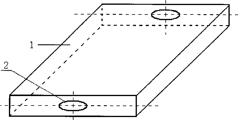
[0018] figure 1 Shown is a blade of the invention with an elliptical autorotation displacement hole. In the figure, proper selection of the long and short axis of the ellipse will directly affect the operation of the blades and even the performance of the entire windmill. Appropriately increasing the length of the minor axis of the ellipse can make the operation of the blade softer, and if the long and minor axes of the ellipse are the same, it becomes a circle. In order to prevent the axial movement between the blade and the blade rotation axis, the method of slotting on the circumference of the ellipse can be adopted, but a cam must be added at the position corresponding to the blade rotation axis and the groove.
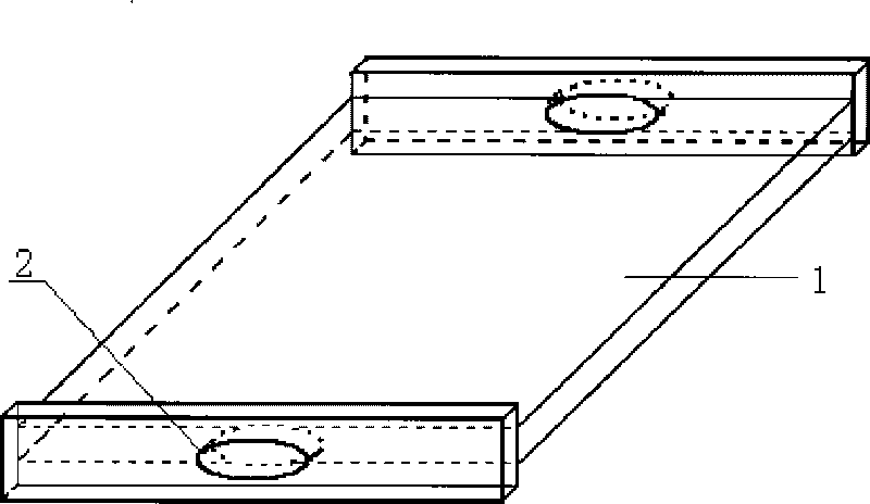
[0019] figure 2 It is a flat blade with an elliptical rotation and displacement hole of the present invention. The flat blade is advantageous when the wind blade is in an upwind state.
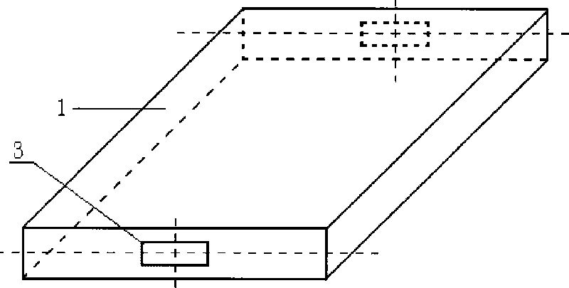
[0020] image 3 It is the blade of the present invention with a rectang...
PUM
 Abstract
Description
Claims
Application Information