
Vehicular lamp

A technology for lamps and vehicles, applied in road vehicles, motor vehicles, cooling/heating devices of lighting devices, etc., can solve problems such as optical design errors of projection lenses, light sources and reflectors, thermal deformation of lens frames, and small heat release. Achieve the effect of avoiding the decline of light distribution performance, improving light distribution performance and avoiding position shift

Inactive Publication Date: 2010-06-23
ICHIKOH IND LTD
View PDF6 Cites 12 Cited by
  • Summary
  • Abstract
  • Description
  • Claims
  • Application Information

AI Technical Summary

Problems solved by technology

[0004] However, in the above-mentioned existing vehicle lamps, although the light source is arranged on the heat sink, the heat dissipation effect around the light source is good, but because the lens frame is made of a separate synthetic resin material, the temperature around the projection lens increases, and there is The lens holder may be slightly thermally deformed due to the temperature difference
[0005] In addition, the above-mentioned semiconductor-type light-emitting element has a smaller heat dissipation compared with a halogen lamp and a HID lamp (high-intensity discharge lamp), so in recent years, a synthetic resin lens that is lighter than a glass lens has been used as a projection lens. When a resin lens is used as the projection lens, there is a possibility that displacement may occur on the projection lens due to the above-mentioned thermal influence.
[0006] In this way, if the lens frame part is slightly displaced or the projection lens itself is slightly deformed due to the influence of heat around the projection lens, a slight error will occur in the optical design of the projection lens, light source and reflector and will affect the light distribution performance. produce adverse effects

Method used


Image

  • Vehicular lamp
  • Vehicular lamp
  • Vehicular lamp

Examples


Embodiment Construction

[0028] Hereinafter, an embodiment of the present invention will be described in detail by taking a vehicle headlight as an example in conjunction with the accompanying drawings.

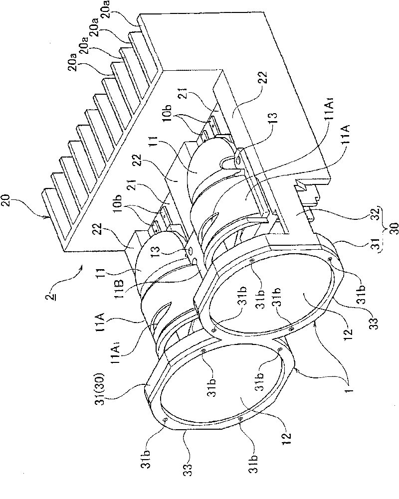
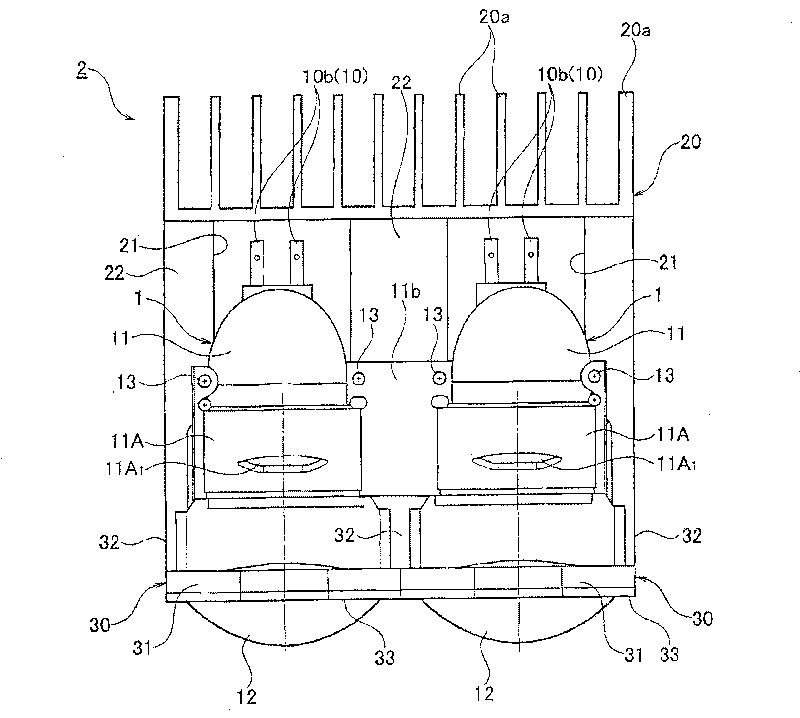
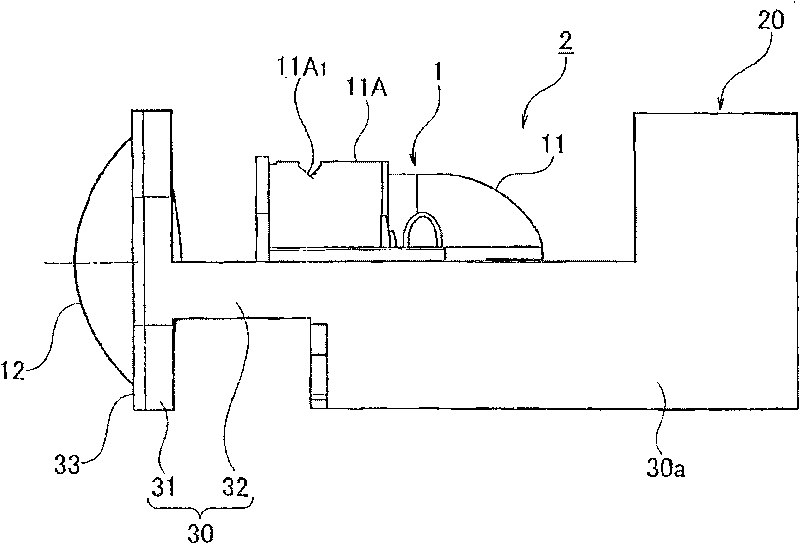
[0029] Figure 1 to Figure 5 The lamp unit of the shown headlight is constituted as a projection type lamp unit using a semiconductor-type light source as a light source, and it is provided with: a semiconductor-type light source 10; Concave reflective surface 11a; projection lens 12, which converges the direct light of semiconductor-type light source 10 and the reflected light of above-mentioned reflector 11 and irradiates to the front of the lamp; heat sink 20, which is connected with semiconductor-type light source 10, reflector 11, projection The lenses 12 are collectively arranged.

[0030] The light source unit 1 is constituted by the semiconductor light source 10 , the reflector 11 , and the projection lens 12 , and the lamp unit 2 is constituted by the combination of the light source unit 1 ...


PUM


Abstract

The invention provides a projection-type vehicular lamp which can improve the whole radiation effect of a light source unit and can eliminate a temperature difference around a light source and a projection lens. The vehicular lamp is provided with a light source, a reflector, a projection lens and a radiating rib, wherein the reflector is provided with a cover part and reflects one part of emergent light of the light source to the front of the lamp; the periphery of the projection lens is kept fixed by a lens carrier; the projection lens converges the direct light of the light source and the reflecting light formed by the reflector and illuminates to the front of the lamp; and the radiating rib integrally arranges the light source, the reflector and the projection lens. The projection-type vehicular lamp is characterized in that the lens carrier and the radiating rib are integrally formed.

Description

technical field [0001] The present invention relates to vehicle lamps used as headlights, rear combination lamps, fog lamps, etc. of automobiles, and particularly relates to a projection type that converges direct light from a light source and reflected light generated by a reflector with a projection lens and illuminates the front of the vehicle lamps for vehicles. Background technique [0002] Conventionally, as a projection type vehicle lamp, there is a product shown in Patent Document 1. This product is constituted by integrally molding a lens holder holding a fixed projection lens and a reflector with a suitable synthetic resin, and mounting it. On the heat sink, a light source including a semiconductor light emitting element such as an LED is arranged on the heat sink to constitute a light source unit. [0003] Patent Document 1: JP-A-2007-109613 [0004] However, in the above-mentioned existing vehicle lamps, although the light source is arranged on the heat sink, t...

Claims


Application Information

Patent Timeline
IPC IPC(8): F21S8/10F21V29/00F21V5/04F21V17/10F21V7/04F21Y101/02F21W101/02F21V29/76F21V29/89F21W107/10
Inventor 川村孝幸
Owner ICHIKOH IND LTD
Learn More