
Light-distribution LED street lamp

A technology of LED light and light distribution, which is applied in the direction of light source, point light source, light source fixation, etc. It can solve the problems of LED light blocking, reducing the light output rate of LED street lights, light distribution effect, light absorption, etc., and achieves convenient production and production , Good light distribution effect, uniform light intensity distribution

Inactive Publication Date: 2012-01-25
ADVANCED OPTRONIC DEVICES CHINA
View PDF1 Cites 0 Cited by
  • Summary
  • Abstract
  • Description
  • Claims
  • Application Information

AI Technical Summary

Problems solved by technology

The lamp head is arc-shaped as a whole, so there is a phenomenon of light blocking of LED lamps with different inclination angles, and there is also a phenomenon of light absorption between adjacent LED lamps, which will inevitably reduce the overall light output rate and light distribution effect of LED street lamps.

Method used


Image

  • Light-distribution LED street lamp
  • Light-distribution LED street lamp
  • Light-distribution LED street lamp

Examples


Embodiment 1

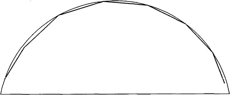
[0043] Embodiment 1, as attached Figure 4 As shown, the LED street lamp includes a base plate 1 and an LED lamp 3. The base plate 1 includes a bottom plane 2. Eight light distribution plates made of cast aluminum materials are arranged on the bottom plane 2. Each light distribution plate has a light distribution surface. LED lights 3 with a power of 1W are fixed on each of the light distribution surfaces, and the eight light distribution surfaces are connected in a zigzag shape in turn to form two light distribution groups. An obtuse angle is formed to the horizontal line. The light distribution surface of the second light distribution group forms an obtuse angle with the opposite horizontal line of the LED street light installation reference plane. The light distribution surfaces of the two light distribution groups are arranged at intervals. The light distribution surfaces installed on each light distribution surface The divergence angle of the LED lamp 3 increases with the...

Embodiment 2

[0045] Embodiment 2, as attached Figure 5 As shown, the LED street lamp includes a base plate 1 and an LED lamp 3. The base plate 1 includes a bottom plane 2. Ten light distribution plates made of cast aluminum materials are arranged on the bottom plane 2. Each light distribution plate has a light distribution surface. A LED lamp 3 with a power of 1W is fixed on each of the light distribution surfaces, and the ten light distribution surfaces are connected sequentially in a zigzag shape to form two light distribution groups. An obtuse angle is formed to the horizontal line. The light distribution surface of the second light distribution group forms an obtuse angle with the opposite horizontal line of the LED street light installation reference plane. The light distribution surfaces of the two light distribution groups are arranged at intervals. The light distribution surfaces installed on each light distribution surface The divergence angle of the LED lamp 3 increases with the...

Embodiment 3

[0047] Embodiment 3, as attached Figure 6 As shown, the LED street lamp includes an LED lamp 3 and a base plate 1 made of cast aluminum material. The base plate 1 includes a bottom plane 2. Eight light distribution plates are arranged on the bottom plane 2. Each light distribution plate has a light distribution surface. The LED lamp 3 with a power of 1W is fixed on the light distribution surface, and the eight light distribution surfaces form two light distribution groups. The light distribution surface of the first light distribution group forms an obtuse angle with the positive horizontal line of the LED street lamp installation reference surface. The light distribution surface of the second light distribution group forms an obtuse angle with the opposite horizontal line of the LED street lamp installation reference plane, the light distribution surfaces of the two light distribution groups are arranged at intervals, and the divergence angle of the LED lights 3 installed on ...


PUM


Abstract

The invention relates to a light-distribution LED street lamp. The light-distribution LED street lamp comprises a plurality of light distribution surfaces, wherein each light distribution surface is provided with a plurality of LED lamps; the light distribution surfaces constitute two light distribution groups; the light distribution surface of the first light distribution group and the forward horizontal line of the erection reference plane form an obtuse included angle, and the light distribution surface of the second light distribution group and the reverse horizontal line of the erection reference plane form an obtuse included angle; the divergence angle of each LED lamp installed on the light distribution surface increases as the obtuse included angle between the light distribution surface and the horizontal line of the erection reference plane increases; the whole lamp cap is in the structure of a plane and has a compact structure; and the thickness of the lamp cap is determinedby the light distribution surface with the maximum angle of inclination. The lamp can be very thin, thereby reducing production cost and eliminating the phenomenon of light blocking of the LED lamps on the light distribution surfaces with different angles of inclination as well as the phenomenon of light absorption among adjacent LED lamps. The light-out rate reaches 90%. Thus, the light-distribution LED street lamp ensures sufficient intensity of illumination on the road surface far away from the light source, and realizes light distribution curves required by different illuminated areas. The light-distribution LED street lamp has the advantages of favorable light distribution effect, and uniform intensity of illumination in the illuminated area.

Description

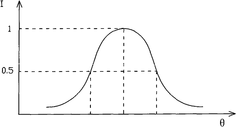
technical field [0001] The invention relates to an LED street lamp, in particular to a LED street lamp with light distribution that makes the lighting curve of the entire light source distributed in a bat-wing shape after light distribution, and belongs to the field of LED lighting. Background technique [0002] In recent years, LED technology has developed rapidly, its luminous efficiency has doubled, and its cost has dropped sharply. LED light sources are widely used in the field of lighting. It has many advantages such as energy saving, environmental protection, and long life. The best way, known as the 21st century green light source, has broad prospects for development. [0003] As a lighting tool, LED street lamps must not only save energy and protect the environment, but also consider the safety and comfort of the lighting environment. This requires scientific and reasonable optical design to make the lamps achieve high efficiency, energy saving, and good lighting qua...

Claims


Application Information

Patent Timeline
Patent Type & Authority Patents(China)
IPC IPC(8): F21V19/00F21W131/103F21Y101/02
CPCY02B20/72
Inventor 孙夕庆李明军王丁民孔瑞
Owner ADVANCED OPTRONIC DEVICES CHINA
Learn More