
Layout method capable of automatically executing layout rule detection for line pair of differential signal

A differential signal and layout method technology, applied in special data processing applications, instruments, electrical digital data processing, etc., can solve problems such as reducing the work efficiency of layout engineers and poor quality of printed circuit boards

Inactive Publication Date: 2010-06-23
嘉兴金日升工具股份有限公司
View PDF0 Cites 3 Cited by
  • Summary
  • Abstract
  • Description
  • Claims
  • Application Information

AI Technical Summary

Problems solved by technology

[0005] The purpose of the present invention is to provide a layout method that can automatically perform the layout rule inspection of differential signal wiring pairs, so as to solve the problem that the conventional layout method is easy to be artificial due to manually confirming the layout rules of differential signal wiring pairs. Negligence, which leads to poor quality of the designed printed circuit board, and avoids reducing the work efficiency of the layout engineer due to human operation

Method used


Image

  • Layout method capable of automatically executing layout rule detection for line pair of differential signal
  • Layout method capable of automatically executing layout rule detection for line pair of differential signal
  • Layout method capable of automatically executing layout rule detection for line pair of differential signal

Examples


Embodiment Construction

[0019] In order to facilitate the comparison with the conventional layout method, and to make readers understand the present invention more easily, the following embodiments will first assume that there is a layout software using the program based on the layout method of the present invention, and at the same time, it will be described in conjunction with the accompanying drawings. The present invention will be described in detail.

[0020] Assuming that a layout engineer is using the layout software, during operation, the layout software will judge whether the layout engineer has further requirements for automatic execution of the layout rule inspection of the differential signal wiring pairs. If it is judged as yes, the layout software will execute the above-mentioned program based on the layout method of the present invention to automatically perform the layout rule check of the differential signal trace pairs. The operation mode of the layout software to automatically perf...


PUM


Abstract

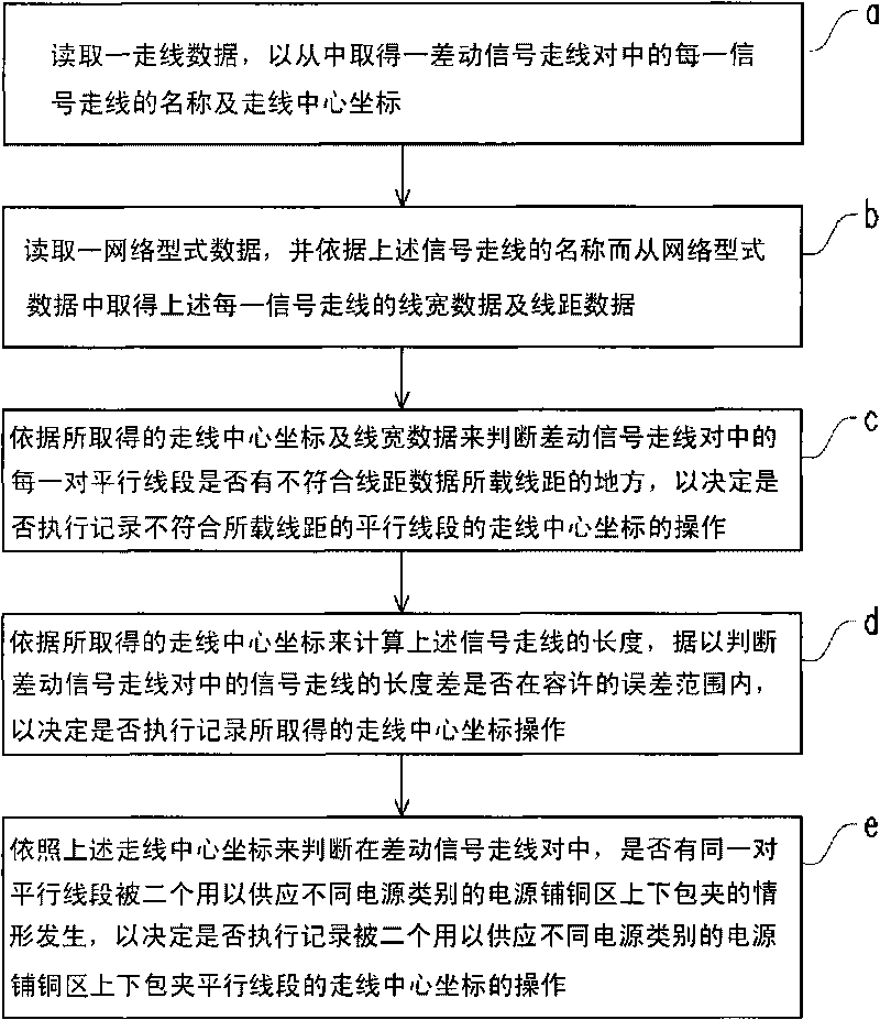
The invention relates to a layout method capable of automatically executing the layout rule detection for a line pair of a differential signal. The method comprises the following steps of: a, obtaining a line name and a line central coordinate of each signal in the line pair of the differential signal from line data; b, obtaining the line width data and the line spacing data of each signal from network-type data according to the line name of the signal; c, judging that whether each pair of parallel line segments in the line pair of the differential signal accord with the line spacing carried by the line spacing data or not according to the obtained the line central coordinate and the line width data; d, calculating the length of the line of the signal according to the obtained the line central coordinate, so as to judge that whether the length of the line of the signal in the line pair of the differential signal is within the allowable error range or not; e, judging that whether the same pair of parallel line segments in the line pair of the differential signal are trapped by two power copper-pouring areas used for supplying different powers according to the obtained the line central coordinate.

Description

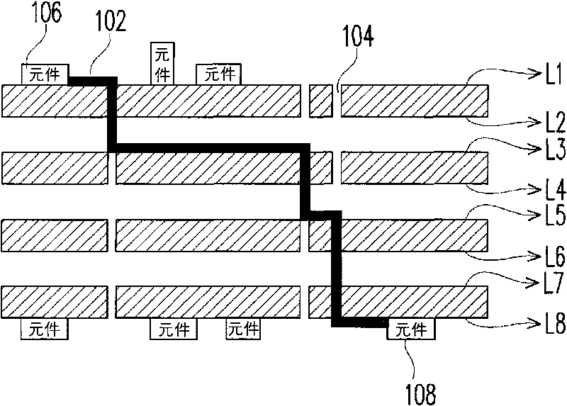
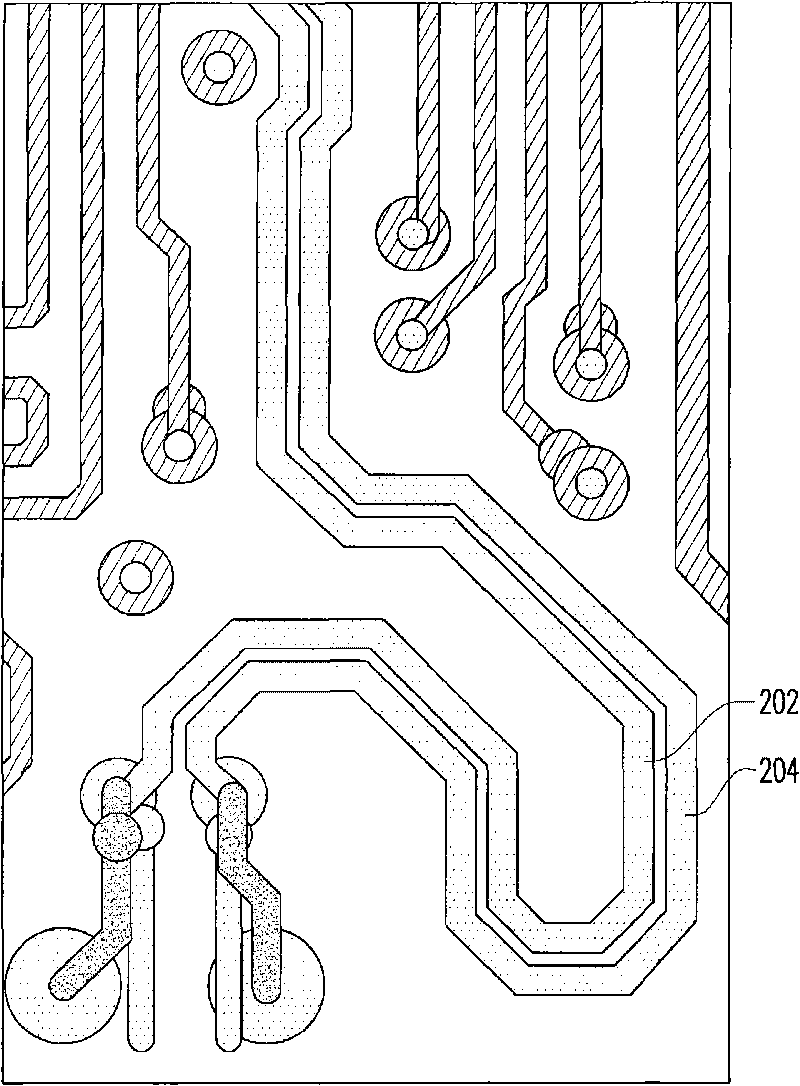
technical field [0001] The present invention relates to a technology in the field of layout, in particular to a layout method. Background technique [0002] In the production of Printed Circuit Board (PCB), in the layout of multi-layer boards, traces are often used to travel between different layers through vias. , so as to connect the components separated on the two surfaces of the circuit board, or connect the components on the surface of the circuit board to the power supply copper area on the inner layer of the circuit board. figure 1 It is a schematic diagram of wiring through a through hole. like figure 1 As shown, the circuit board is divided into eight layers for wiring, which are respectively marked as L1-L8, and the wiring 102 connects the components 106 and 108 through through holes (as shown by the label 104 ). [0003] In some special circuit designs, differential traces are used for layout. A differential signal wiring pair is a very special signal in a pri...

Claims


Application Information

Patent Timeline
Patent Type & Authority Applications(China)
IPC IPC(8): G06F17/50
Inventor 张有权阮于绫林明慧
Owner 嘉兴金日升工具股份有限公司
Learn More