Electrode terminal connection structure and power battery pack using same

An electrode terminal and connection structure technology, applied in the field of electrode terminal connection structure, can solve the problems such as reliability affecting the popularization of electric vehicles, rigid connection structure susceptible to impact, and inability to quickly achieve fusing, etc. Reliability, the effect of optimizing electrical conductivity

Active Publication Date: 2012-11-21
BYD CO LTD
View PDF1 Cites 0 Cited by
  • Summary
  • Abstract
  • Description
  • Claims
  • Application Information

AI Technical Summary

Problems solved by technology

[0005] In the above-mentioned prior art, there is a relatively prominent shortcoming, that is, the connection structure of the above-mentioned electrode terminals adopts a mechanical rigid connection. Various shaking, vibration, and even collisions will occur during driving. The rigid connection structure between the electrode terminals is easily damaged by impact, and thus becomes loose and disconnected, resulting in the failure of the power battery pack and the inability of the electric vehicle to run. In the prior art, the reliability of the electrode terminal connection structure is a shortcoming that affects the popularization of electric vehicles
In addition, in the above-mentioned prior art, the overcurrent protection of the power battery pack is carried out by using a low-melting-point solder with a fusing temperature of 200-300 degrees and mainly composed of tin. Tension, resulting in the inability to quickly achieve the purpose of fusing

Method used


Image

  • Electrode terminal connection structure and power battery pack using same
  • Electrode terminal connection structure and power battery pack using same
  • Electrode terminal connection structure and power battery pack using same

Examples


Embodiment approach

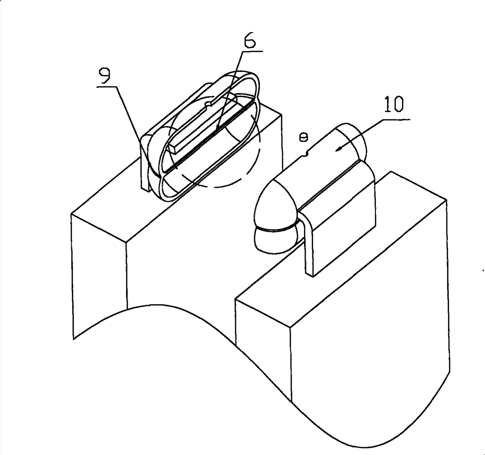
[0036] The traditional electrode terminal connection structure such as Figure 9 As shown, the electrode terminals 1 are filled with a solid conductive medium 5, and through rigid connection, different electrode terminals 1 are electrically connected. As mentioned above, this kind of rigid connection cannot guarantee the reliability of the connection of the electrode terminal 1. When this electrode terminal connection structure is applied to the power battery pack of the car, various shaking, vibration, Even in a collision, the rigid connection structure between the electrode terminals 1 is easily damaged by impact, thereby loosening and disconnecting, causing the power battery pack to fail to work, and the electric vehicle to be unable to drive. Therefore, in the prior art, the electrode terminal connection structure The reliability is a more prominent shortcoming.

[0037] In this prior art, when the current increases, since the current conduction capability of the conducti...

specific Embodiment approach 1

[0039] This embodiment is an embodiment in which the electrode terminal 1 is located on the upper surface of the power battery pack during operation of the power battery pack.

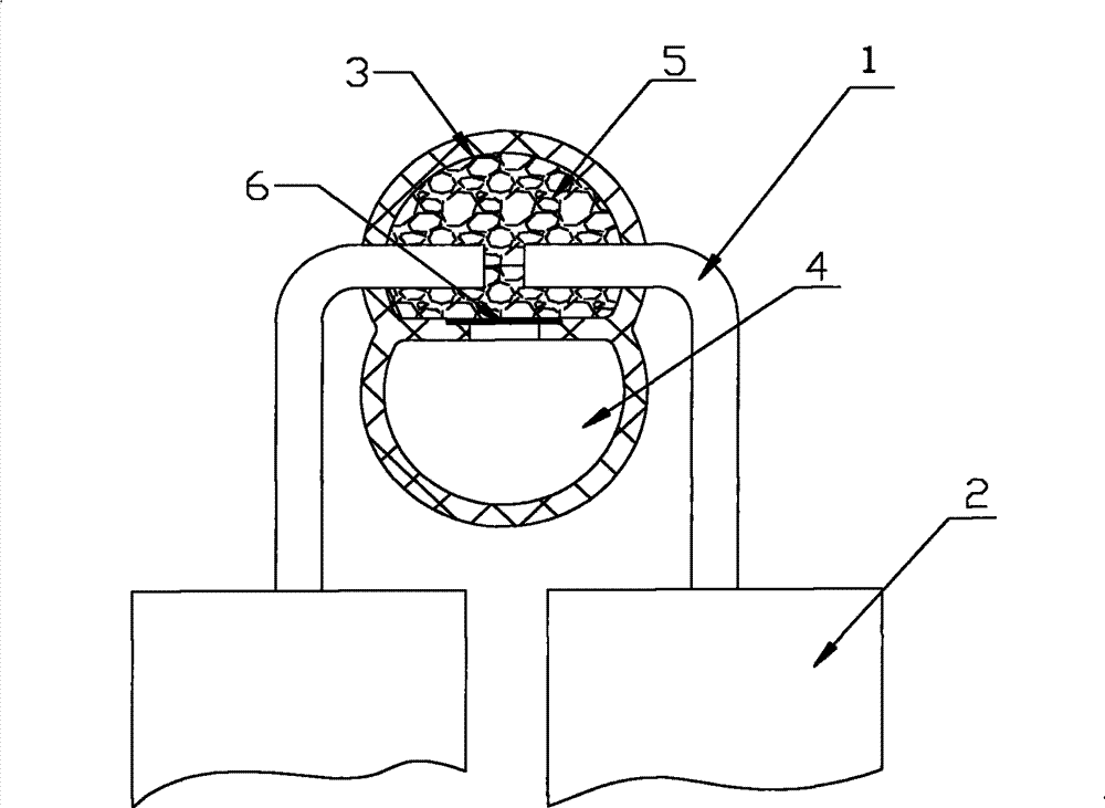
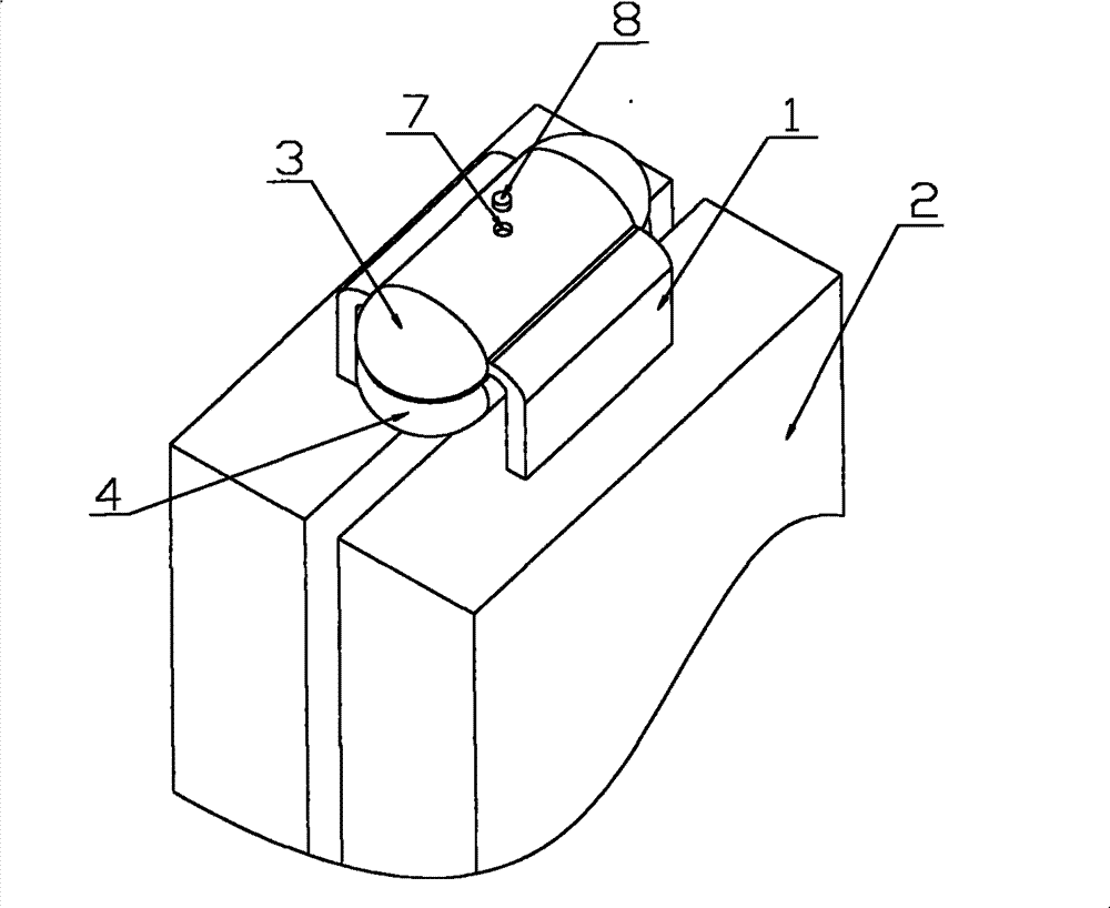
[0040] Such as Figure 1 to Figure 4 As shown, the electrode terminal 1 is sealed and connected by the conductive cavity 3, the collecting cavity 4 is arranged under the conductive cavity 3, the lower side of the conductive cavity 3 is provided with an opening, and is separated from the collecting cavity 4 by a separator 6, from the conductive cavity 3 A conductive medium 5 is added to the conductive medium addition hole 7 above, and finally the sealing plug 8 is sealed to the conductive medium additive hole 7 .

[0041]Wherein, the melting temperature of the separator 6 is 100°C-350°C, so that the electrode terminal connection structure can be melted when the overheating temperature reaches 100°C-350°C. Of course, the melting temperature of the separator 6 can also be determined according to the actua...

specific Embodiment approach 2

[0050] This embodiment is an embodiment in which the electrode terminal 1 is located on the side of the power battery pack during operation of the power battery pack.

[0051] Such as Figure 5 to Figure 8 As shown, the electrode terminal 1 is sealed and connected by the conductive cavity 3, and the collecting cavity 4 is arranged under the conductive cavity 3. 7 Add the liquid conductive medium 5, and finally seal the sealing plug 8 on the conductive medium additive hole 7.

[0052] When the current increases, the heat generated by the liquid conductive medium 5 is greater, and the temperature rises rapidly. When the temperature rises to a certain level, the separator 6 melts, and the conductive medium 5 flows from the conductive cavity 3 to the collection cavity 4, so that the electrodes There is no liquid conductive medium 5 between the terminals 1, and the circuit is disconnected, which prevents further thermal response and avoids thermal runaway.

[0053] It can be seen...


PUM


Abstract

The invention provides a new electrode terminal connection structure which uses liquid conducting medium (5) for connection. The electrode terminal connection structure comprises electrode terminals which are connected mutually and a sealed conductive cavity (3), wherein the liquid conducting medium (5) is filled in the conductive cavity (3), the electrode terminals are separately inserted in theconductive cavity (3) and connected through the liquid conducting medium (5). The invention uses the liquid conducting medium (5) to perform electrical connection so that when in use, whether how a vehicle using a power battery pack with the electrode terminal connection structure swings, shakes or does any movement, the reliability of the electrode terminal connection structure can not be affected. In addition, the invention also provides the power battery pack using the electrode terminal connection structure.

Description

technical field [0001] The present invention relates to an electrode terminal connection structure, more specifically, to an electrode terminal connection structure for connecting single cells to form a power battery pack. In addition, the present invention also relates to a power battery pack using the electrode terminal connection structure. Background technique [0002] With the shortage of oil and the improvement of people's requirements for environmental protection, electric vehicles and hybrid vehicles are increasingly showing their superiority. As the core power source of electric vehicles - the power battery pack, its importance is particularly prominent. At present, lithium-ion batteries have become the preferred power source for people because of their safety, small size, and high energy density. A power battery pack can be formed by connecting multiple single batteries in series or in parallel. [0003] When a single battery forms a power battery pack, the elect...

Claims


Application Information

Patent Timeline
Patent Type & Authority Patents(China)
IPC IPC(8): H01M2/20H01M50/502H01M50/521H01M50/581
CPCY02E60/12Y02T10/7005Y02T10/7011Y02E60/10
Inventor 郑卫鑫
Owner BYD CO LTD
Why Eureka
Try Eureka