Three-dimensional photoetching method for antenna manufacture

A three-dimensional, lithography technology, applied in antennas, antenna parts, optics, etc., can solve the problems of difficult production and assembly of RF components, unstable coordination relationship, and changes in RF performance, reducing raw material costs, shortening design cycles, Make simple effects

Inactive Publication Date: 2010-06-23
SHANGHAI AMPHENOL AIRWAVE COMM ELECTRONICS CO LTD
View PDF4 Cites 10 Cited by
  • Summary
  • Abstract
  • Description
  • Claims
  • Application Information

AI Technical Summary

Problems solved by technology

[0005] 1. Due to their unstable cooperation relationship, sometimes it will cause large changes in radio frequency performance, resulting in instability in production;
[0006] 2. Since many radio frequency components and substrate fixing brackets must present a three-dimensional geometric shape, some radio frequency components with more complex shapes are difficult to produce and assemble
[0012] The disadvantage of this method is that it can only be carried out on a single surface of a flat plate.

Method used


Image

  • Three-dimensional photoetching method for antenna manufacture
  • Three-dimensional photoetching method for antenna manufacture
  • Three-dimensional photoetching method for antenna manufacture

Examples


Embodiment Construction

[0036] Describe in detail below in conjunction with accompanying drawing.

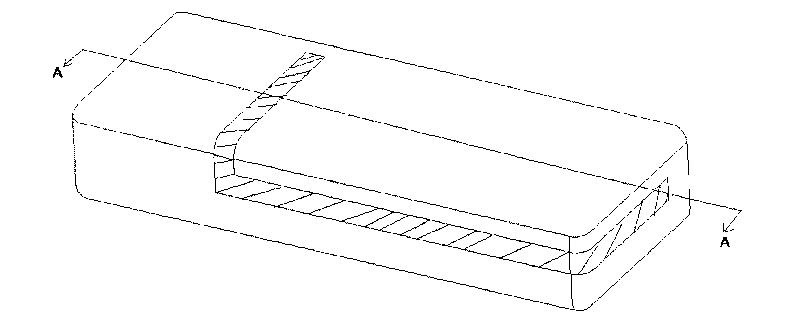
[0037] figure 1 It is the final schematic diagram of the present invention. figure 1 The shaded part of is the shape of the antenna. It can be seen that the shape of the antenna is distributed on three planes, which is three-dimensional. Therefore, the present invention is to complete the fabrication of three-dimensional antennas at one time, rather than only for two-dimensional planes. The fabrication of two-dimensional planar antennas is a special case of this method. The antenna pattern in this example is arbitrary, and its specific production aspects are as follows:

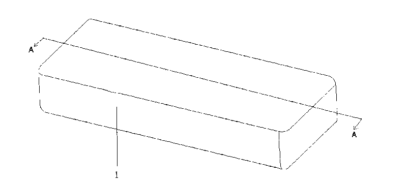
[0038] first step, such as figure 2 , providing a base structural member 1 .

[0039] The base structural member 1 can be made of metallizable plastic such as ABS, etc., by traditional techniques such as injection molding, and its shape can be customized as required. The base structural member 1 is three-dimensional, and any th...


PUM


Abstract

The invention relates to a three-dimensional photoetching method for antenna manufacture, which comprises the following steps: proving a basic structural element; forming a conductive layer on the surface of the basic structural element; forming a photosensitive printing ink layer outside the conductive layer; and carrying out the processes of shielding, light exposure, development and etching. The invention is characterized in that the basic structural element is a three-dimensional structural element, and in addition, the formed conductive layer, the photosensitive printing ink layer formed outside the conductive layer and the shielding and the light exposure processes are all carried on the three-dimensional surface. In the invention, patterns of the three-dimensional antenna can be formed in one step, the production period can be shortened, and the requirement of mass production is met.

Description

technical field [0001] The invention relates to a manufacturing method of an antenna, in particular to a photolithography manufacturing method suitable for the antenna in a wireless communication device. Background technique [0002] The role of the antenna in the mobile communication terminal is to transmit the radio frequency signal generated by the circuit board and transmit the received radio frequency signal to the circuit board, so as to realize the wireless two-way transmission of voice signal, video signal and data. [0003] At present, most mobile communication terminals, especially in mobile phones, PDAs, and laptop computers, use built-in antennas placed inside the terminals. Since the size of the antenna is related to frequency, it must have a certain size and height to There is sufficient radiation efficiency to ensure efficient transmission and reception of electromagnetic waves, resulting in the antenna being one of the largest components in a mobile communica...

Claims


Application Information

Patent Timeline
Patent Type & Authority Applications(China)
IPC IPC(8): H01Q1/00H01Q1/38G03F7/00
Inventor 宋玉明欧立文张新山卢晓峰戴丰于松涛唐永玲
Owner SHANGHAI AMPHENOL AIRWAVE COMM ELECTRONICS CO LTD
Why Eureka
Try Eureka