
Decomposer uninterrupted power supply electric cabinet

A technology of decomposition tank and electric control box, which is applied in the direction of emergency power supply arrangement, substation/power distribution device shell, electrical components, etc., to achieve the effect of convenient maintenance and troubleshooting, troubleshooting or maintenance problems, and clear functions

Active Publication Date: 2010-06-23
GUIYANG AL-MG DESIGN & RES INST
View PDF0 Cites 3 Cited by
  • Summary
  • Abstract
  • Description
  • Claims
  • Application Information

AI Technical Summary

Problems solved by technology

Once a fault or a precursor to a fault is found, first switch to the spare electric control box, remove the faulty electric control box that needs to be replaced, and replace it with a debugged electric control box, and check the cause of the fault of the replaced electric control box later After the maintenance and debugging are completed, it can be used as a spare box for other electric control boxes, so that faults or maintenance problems can be quickly solved, and the safe and reliable operation of the electric control system of the tank stirring motor is ensured.

Method used


Image

  • Decomposer uninterrupted power supply electric cabinet
  • Decomposer uninterrupted power supply electric cabinet
  • Decomposer uninterrupted power supply electric cabinet

Examples


Embodiment Construction

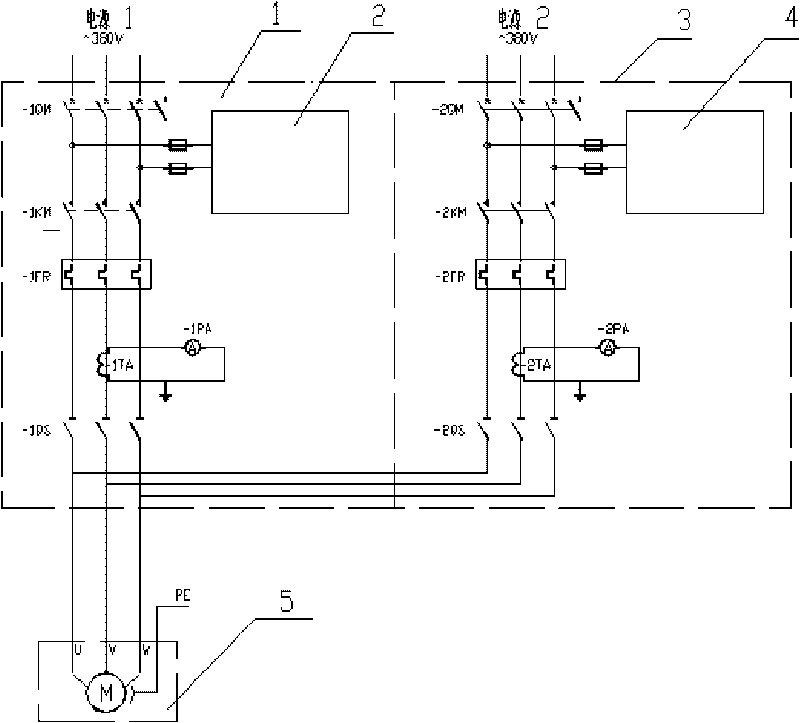
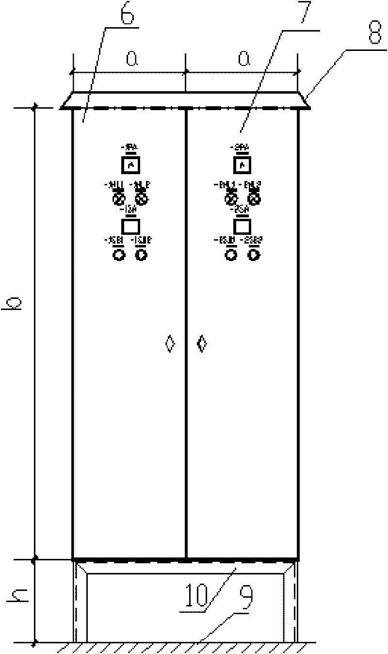
[0015] Embodiment of the present invention: first divide the power distribution control system into independent first power supply circuit 1 and second power supply circuit 2 according to the design drawings, and then install the components of the first power supply circuit 1 and the second power supply circuit 2 respectively Arranged in two independent control boxes, that is, the first power circuit 1 and the first control unit 3 are installed in the first electric control box 6, and the second power circuit 2 and the second control unit 4 are installed in the second electric control box Inside the box 7; the first electric control box 6 and the second electric control box 7 are installed on the channel steel support 10, and the channel steel support 10 is connected with the top of the decomposition tank 9. A rainproof cover 8 is arranged on the top of the first electric control box body 6 and the second electric control box body 7 .

[0016] Wherein, the cables between the f...


PUM

PropertyMeasurementUnit
sizeaaaaaaaaaa
heightaaaaaaaaaa

Abstract

The invention discloses a decomposer uninterrupted power supply electric cabinet, comprising a stirring motor (5), wherein the stirring motor (5) is connected with a first power circuit (1) and a second power circuit (2) respectively, the first power circuit (1) is connected with a first control unit (3), the second power circuit (2) is connected with a second control unit (4), the first power circuit (1) and the first control unit (3) are installed in a first electric cabinet body, the second power circuit (2) and the second control unit (4) are installed in a second electric cabinet body, the first electric cabinet body and the second electric cabinet body are installed on a channel steel support, the channel steel support is connected with the top of a decomposer, rain covers are arranged on the tops of the first electric cabinet body and the second electric cabinet body, and the physical dimension of the second electric cabinet body is the same with the physical dimension of the first electric cabinet body. The invention has the advantages of simple structure, easy replacement, good using effect, convenient overhauling and maintenance, and high safety.

Description

technical field [0001] The invention relates to an electric control device for a decomposition tank of an alumina plant, in particular to an electric control box for power distribution and control of a stirring motor of a decomposition tank of an alumina plant. Background technique [0002] The alumina production process is composed of various physical and chemical processes, and its production process is long and belongs to continuous production process. The decomposition tank is a very important equipment in the alumina production process. After the slurry is stirred by the tank mixer, it is input into the next production process. If it stops working due to the failure of the stirring motor, the normal production of the entire factory will be greatly affected or even completely shut down. At the same time, in order to avoid the solidification of the slurry in the tank, it must be discharged on the spot. Seriously affect the sanitation of the surrounding environment. [...

Claims


Application Information

Patent Timeline
Patent Type & Authority Applications(China)
IPC IPC(8): H02J9/04H02B1/28H02B1/50H05K5/00H05K5/02C01F7/02
Inventor 于杨
Owner GUIYANG AL-MG DESIGN & RES INST
Learn More