Drive of light emitting diode (LED) light source

A technology of LED light source and driver, which is applied in the field of LED light source and can solve problems such as the short board of LED driver quality

Inactive Publication Date: 2010-06-23
四川锦明光电股份有限公司
View PDF2 Cites 23 Cited by
  • Summary
  • Abstract
  • Description
  • Claims
  • Application Information

AI Technical Summary

Problems solved by technology

However, it did not solve the problem of the above-mentioned short board of LED driver quality

Method used


Image

  • Drive of light emitting diode (LED) light source
  • Drive of light emitting diode (LED) light source
  • Drive of light emitting diode (LED) light source

Examples


Embodiment 1

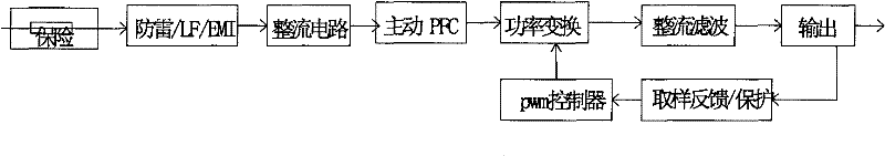
[0054] Such as figure 2 As shown, a driver for an LED light source includes a main circuit, and the main circuit includes:

[0055] The first rectification circuit, the input end of which is connected to the mains, converts the mains from AC to pulsating DC;

[0056] Active PFC, connected in series to the output circuit of the first rectifier circuit, corrects the phase of the input voltage and current through high-frequency pulse switching, so as to improve the power factor of the entire power supply;

[0057] The first power conversion circuit is connected in series to the output circuit of the active PFC, and the high-voltage pulse current is converted into low-voltage and high-current alternating current through a power transformer, and at the same time, high-voltage and low-voltage electrical isolation is provided;

[0058] The first rectification filter circuit is connected in series to the output circuit of the first power conversion circuit, and converts the high-fre...

Embodiment 2

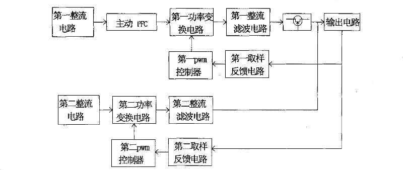
[0071] Such as image 3 As shown, a driver for an LED light source includes a main circuit, and the main circuit includes:

[0072] The first rectification circuit, the input end of which is connected to the mains, converts the mains from AC to pulsating DC;

[0073] Active PFC, connected in series to the output circuit of the first rectifier circuit, corrects the phase of the input voltage and current through high-frequency pulse switching, so as to improve the power factor of the entire power supply;

[0074] The first power conversion circuit is connected in series to the output circuit of the active PFC, and the high-voltage pulse current is converted into low-voltage and high-current alternating current through a power transformer, and at the same time, high-voltage and low-voltage electrical isolation is provided;

[0075] The first rectification filter circuit is connected in series to the output circuit of the first power conversion circuit, and converts high-frequenc...

Embodiment 3

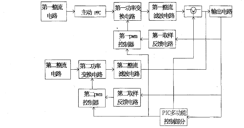
[0089] Such as Figure 4 As shown, a driver for an LED light source includes a main circuit, and the main circuit includes:

[0090] The first rectification circuit, the input end of which is connected to the mains, converts the mains from AC to pulsating DC;

[0091] Active PFC, connected in series to the output circuit of the first rectifier circuit, corrects the phase of the input voltage and current through high-frequency pulse switching, so as to improve the power factor of the entire power supply;

[0092] The first power conversion circuit is connected in series to the output circuit of the active PFC, and the high-voltage pulse current is converted into low-voltage and high-current alternating current through a power transformer, and at the same time, high-voltage and low-voltage electrical isolation is provided;

[0093] The first rectification filter circuit is connected in series to the output circuit of the first power conversion circuit, and converts high-frequen...


PUM


Abstract

The invention discloses a driver of a light emitting diode (LED) light source, comprising a main circuit and a backup circuit. A loop of a first rectifier and filter circuit of the main circuit is also connected with a field-effect tube in series, and the field-effect tube is connected with an output circuit. The field-effect tube is used as an electronic switch to finish the switching between the main circuit and the backup circuit, and prevents a rectifier diode in the first rectifier and filter circuit from influencing the backup circuit after short circuit. In the invention, the backup circuit also comprises a programmable logic controller (PLC) multifunctional control part. The invention has the technical effects of improving the reliability of the system, reducing the cost, intelligently adjusting the output power, and the like.

Description

technical field [0001] The present invention mainly relates to an LED light source, in particular to a driver for the LED light source. Background technique [0002] LED light source is more and more used in various occasions due to its high efficiency, energy saving, long life and environmental protection (without halogen elements). Now, the life of a well-designed LED light source can reach 50,000 hours, and more than 90% of the light-off failures are caused by the damage of the driver. It is a very important research problem to improve the life of the LED driver, eliminate the short board of quality, and balance the life of each part of the whole product. [0003] The traditional LED power driver generally adopts the attached figure 1 The scheme: [0004] The main functional components are [0005] 1. Insurance: It is used to disconnect the entire power supply circuit when the entire lamp is short-circuited, so as not to affect the entire power supply system and cause ...

Claims


Application Information

Patent Timeline
Patent Type & Authority Applications(China)
IPC IPC(8): H05B37/02
Inventor 卿晓辉成军徐文洪邓陵泉
Owner 四川锦明光电股份有限公司
Why Eureka
Try Eureka