Dual-bulb tube high-voltage oil tank

A high-pressure fuel tank and bulb technology, applied in X-ray equipment, electrical components, etc., can solve problems such as complex structure, achieve small size, improve X-ray quality, and reduce ripple

Inactive Publication Date: 2010-06-23
NEUSOFT MEDICAL SYST CO LTD
View PDF0 Cites 13 Cited by
  • Summary
  • Abstract
  • Description
  • Claims
  • Application Information

AI Technical Summary

Problems solved by technology

The high-pressure switching circuit uses a high-pressure switching valve, which has a complex structure

Method used


Image

  • Dual-bulb tube high-voltage oil tank
  • Dual-bulb tube high-voltage oil tank
  • Dual-bulb tube high-voltage oil tank

Examples


Embodiment Construction

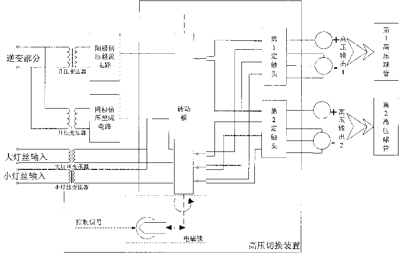
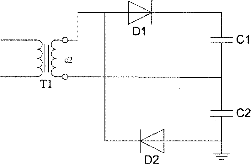
[0017] like figure 1 , 2 As shown, the double-tube high-pressure fuel tank of the present invention is installed in the X-ray high-voltage generator, and is provided with a voltage doubler rectifier circuit in the high-pressure fuel tank (i.e. figure 1 The anode voltage doubler rectifier circuit and cathode doubler rectifier circuit), step-up transformer, filament transformer and high voltage switching device are all immersed in insulating oil. There is also an insulating framework inside the oil tank, on which the voltage doubler rectifier circuit, step-up transformer, filament transformer and high-voltage switching device are all fixedly installed, which can ensure reliable insulation between each part and between each part and the tank. The primary winding of the step-up transformer is connected to the inverter part of the high-voltage generator, and the voltage output by the inverter part is boosted and then output to the voltage doubler rectifier circuit through the seco...


PUM


Abstract

The invention relates to a dual-bulb tube high-voltage oil tank arranged in an X-ray high-voltage generator. The high-voltage oil tank is provided with a voltage-multiplying rectification circuit, a boosting transformer, a filament transformer and a high-voltage switching device, wherein a primary winding of the boosting transformer is connected with an inversion part of the high-voltage generator; the voltage output by the inversion part is boosted and output to the voltage-multiplying rectification circuit through the primary winding; the high-voltage direct-current voltage output by the voltage-multiplying rectification circuit is transmitted to a first high-voltage bulb tube and a second high-voltage bulb tube through the high-voltage switching device. The invention ensures participation in high-voltage generator resonance, adopts voltage-multiplying rectification circuit, has a high resonance frequency of 80-250kHz and little output high voltage ripple, improves the quality of X ray emitted by the bulb tube, ensures that the filament current frequency output by the dual-bulb tube high-voltage oil tank is 40kHz so as to improve the definition of perspective and exposure images, is small in size to realize effective isolation between strong current and weak current.

Description

technical field [0001] The invention relates to a medical diagnostic X-ray high-voltage generator, in particular to a double-tube high-pressure oil tank. Background technique [0002] The high-frequency and high-voltage generator technology of foreign X-ray machines developed earlier. In the 1980s, intermediate-frequency X-ray machines were launched, and high-frequency X-ray machines were launched in the 1990s. The operating frequency of the high-voltage generators was increased from 50 Hz to hundreds of hertz. , Thousands of Hertz, Tens of Thousands of Hertz. The increase in operating frequency has brought about a qualitative leap in structure and performance. Due to the use of the latest semiconductor devices, high-frequency conversion technology, closed-loop control technology and microcomputer management, the problems existing in traditional power frequency and intermediate frequency X-ray machines have been solved, and the protection level, imaging quality and doctor's...

Claims


Application Information

Patent Timeline
Patent Type & Authority Applications(China)
IPC IPC(8): H05G1/10
Inventor 王维重王凯管恩振
Owner NEUSOFT MEDICAL SYST CO LTD
Why Eureka
Try Eureka