Image diagnosis apparatus and image diagnosis method

An image diagnosis and image technology, which is applied in the direction of diagnosis, measurement device, diagnosis recording/measurement, etc., can solve the problem of insufficient effect, insufficient position resolution of PET and position alignment, and no quantitative determination of position deviation between PET image and CT image. Migration methods or indicators and other issues

Active Publication Date: 2010-06-30
TOSHIBA MEDICAL SYST CORP
View PDF0 Cites 12 Cited by
  • Summary
  • Abstract
  • Description
  • Claims
  • Application Information

AI Technical Summary

Problems solved by technology

In addition, even if a breathing protocol with a small position shift is used, the effect may not be sufficient in some cases.
Or, sometimes the breathing method requested by the subject cannot be carried out
Furthermore, the calibration method of physically measuring the positional displacement may not be able to perform accurate positional alignment due to insufficient PET positional resolution (approximately 5mm)
[0009] In this way, although various methods have been proposed to solve the positional offset between PET images and CT images, sometimes they cannot effectively function
Moreover, there is no method or index to quantitatively measure the positional offset between PET images and CT images in the human body

Method used


Image

  • Image diagnosis apparatus and image diagnosis method
  • Image diagnosis apparatus and image diagnosis method
  • Image diagnosis apparatus and image diagnosis method

Examples


no. 1 Embodiment approach

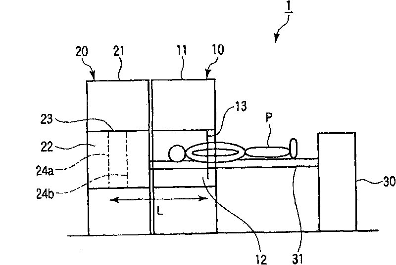
[0038] figure 1 It is a side view schematically showing the appearance of the imaging diagnostic apparatus (PET-CT apparatus) according to the first embodiment of the present invention.

[0039] Such as figure 1 As shown, the image diagnosis apparatus 1 has: an X-ray CT (Computed Tomography) apparatus 10 , a PET (Positron Emission Tomography) apparatus 20 , and a bed apparatus 30 .

[0040] The X-ray CT apparatus 10 is equipped with a CT gantry 11 . The PET device 20 is equipped with a PET rack 21 . The CT gantry 11 and the PET gantry 21 maintain a predetermined positional relationship, are adjacent to each other, and are connected in a detachable manner. A hollow portion 12 is formed in the CT gantry 11 . A hollow portion 22 is formed in the PET rack 21 . The CT gantry 11 and the PET gantry 21 are arranged such that the centerline of the hollow portion 12 approximately coincides with the centerline of the hollow portion 22 .

[0041] In this way, the X-ray CT apparatus ...

no. 2 Embodiment approach

[0115] Next, a second embodiment of the present invention will be described. In addition, in the following description, the same code|symbol is attached|subjected to the structural element which has substantially the same function as 1st Embodiment, and it repeats description only when necessary.

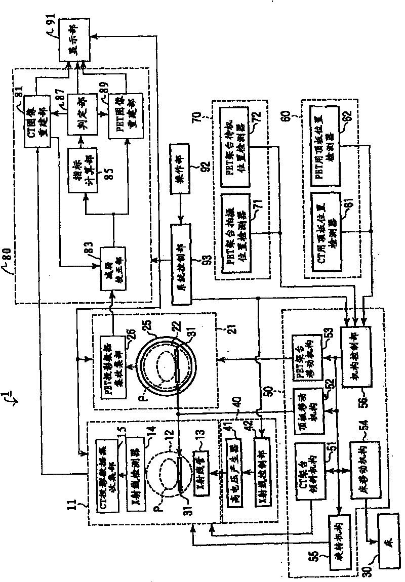
[0116] Figure 12 It is a system block diagram of the diagnostic image apparatus 2 of the second embodiment. Such as Figure 12 As shown, the image generation unit 800 of the diagnostic image apparatus 2 includes a CT image reconstruction unit 81 , an attenuation correction unit 83 , an index calculation unit 85 , and a PET image reconstruction unit 89 . when with figure 2 As can be seen from the comparison, the image generating unit 800 of the second embodiment does not include the determination unit 87 included in the image generating unit 800 of the first embodiment.

[0117] The CT image reconstruction unit 81 reconstructs a CT image. Data of the CT image is supplied to th...


PUM


Abstract

A detector detects gamma-rays emitted from inside an imaging region. An acquisition unit acquires a plurality of first projection data sets associated with a plurality of projection angles via the detector. An attenuation-correction unit attenuation-correct the plurality of first projection data sets based on a first CT image associated with the imaging region to generate a plurality of second projection data sets associated with the plurality of projection angles. An index calculation unit calculates an index based on the plurality of second projection data sets. The index is corresponding to a degree of positional offset between the imaging region at the time of acquisition of a plurality of third projection data sets associated with the first CT image and the imaging region at the time of acquisition of the plurality of first projection data sets.

Description

[0001] Cross References to Related Applications [0002] This application is based on and claims priority from a prior Japanese application No. 2008-328027 filed on December 24, 2008, the entire contents of which are hereby incorporated by reference. technical field [0003] The present invention relates to an image diagnosis device and an image diagnosis method for performing image diagnosis by combining PET (Positron Emission Tomography) and X-ray CT (Computed Tomography). Background technique [0004] There is an imaging diagnostic apparatus that performs image diagnosis by combining PET and X-ray CT (hereinafter referred to as a PET-CT apparatus). A PET-CT device is a device obtained by integrating a PET device and an X-ray CT device using the same bed. The cross section of the PET image and the cross section of the CT image are set so as to be physically consistent. [0005] However, since the PET image and the CT image cannot be taken at the same time, there may be a...

Claims


Application Information

Patent Timeline
Patent Type & Authority Applications(China)
IPC IPC(8): A61B5/00A61B6/03
CPCA61B6/5235A61B6/037G01T1/00G06T11/005A61B6/032A61B6/583
Inventor 本村信笃金田明义
Owner TOSHIBA MEDICAL SYST CORP
Why Eureka
Try Eureka